Jump to content
SAU Community

Recommended Posts

Are there any golden rules with the water feed and return, lately I've thought the engine smells warm after shut down,( turbo really) when you come back 5-10 minutes later..

recently I replaced the braided line water feed with a hard pipe take off from turbo, due to what I thought was a damaged braided line due to heat.

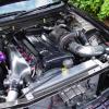
As you might be able to see I've had to bend the hard down a bit to fit it between engine and turbo, Is that going effect the feed considering its just gravite feed once engine is shut down, or is it more syfin? (Spelling?)

whats got me wondering is when I took the braided line off to replace with hard pipe, the turbo was bone dry, and I just checked it now ( unscrewed hard pipe) it wasn't dry but coolant didn't pour out everywhere?

post-48287-0-56927200-1334484620_thumb.jpg

Link to comment
https://www.sau.com.au/forums/topic/397810-water-feed-for-turbo/
Share on other sites

Few manufacturers these days go with high mounts and one of the reasons is that a turbo (or anything) will act as a gas trap and when coolant boils it changes state to a gass .

To have a turbo water cooling system work properly the turbo can't be the highest point in the cooling system , steam bubles need to rise out of the turbos core but if theres no where to go they just displace the coolant fluid and everything up there stays hot .

Manufacturers like Subaru with EJs fit a header tank which becomes the highest point in their cooling systems and the pressure cap goes on top of that . It gives hot water and any steam bubbles somewhere to go so that the turbo is always full of water which can thermosiphon out and be replaced by rising cooler fluid .

The critical time for a turbo is at engine shut down because there is a considerable amount of heat stored in cast exhaust manifolds and turbine housings . Now because the oil and water pumps have stopped all thats left to keep the turbos core at a sane temperature level (to preven any oil cooking) is the water coolant . It takes a lot of heat energy to boil water but when it does and becomes a gas (steam) it can't absorb any more heat from cooling jackets . Therefore it needs to be replaced by cooler water and it needs to move to transfer the heat it absorbs somewhere where it isn't a problem ie radiator tank or preferably an overflow reservoir .

I learnt about water cooled turbo systems by having one fitted to an FJ20 which in std form doesn't have it .

Found water low on the block (block drain plug hole) and returned water from the turbo at a drilled and tapped hole in the head just on the engine side of the thermostat (FJs have the thermostat at the top hose not the bottom like an RB) . So we sourced water at the lowest coolest point in the cooling system and returned the hot stuff at the highest hottest point . It doesn't matter if the coolant is pumped or not through the turbo because the issue is really only at shut down and then the water pump isn't doing anything anyway . So long as the turbo water lines aim vaguely uphill to the highest point the system will work . On my old Bluebirds FJ you could hear the water boiling and the steam bubbles gurgling up the high pipe to the thermostat bowl on the head . From there they went out through the open thermostat and up the main hose to the radiator . I was using an R32 GTR radiator so from its cap overflow the bubbles ended up in the overflow bottle . Generally it only took about three minutes of this water cycling to protect the turbos core .

You can save a lot of money by using second hand or new steel lines banjos and bolts off SR20s because these fit Garrett BB turbos from GT2554R up to GT3582R . You carefully cut and bend the steel tubes to form the shape you want and the steel tube only has to reach beyond the worst of the turbos and manifolds radiated heat . Then you simply use good quality EFI rubber fuel hose to plumb the cooling to the waters source and return points .

Matter of opinion but I reckon aftermarket banjos and braided lines are expensive and look very non standard , the banjos tend to be bulky which makes them awkward to work with because its not really their intended application . Often everything attached to a turbocharger is a pain in the ass to work on in often cramped spaces so this is one area that you can reduce the agro if you try .

From memory std hitachi turbos and large framed Garrett ones use the same sized banjos and bolts as VLs do so factory type stuff is available . Sometimes you have to shorten up the threaded sectons of the banjo bolts if they bottom out before clamping up on the crush washers but a vice and saw fixes that .

Hope this helps , cheers A .

Edited by discopotato03

thanks Disco that does help, sounds like I need a cooling system header tank in one of the turbo lines,( turbo does seem to the highest point ) shouldn't really matter which side of the turbo its on should it ? as once the motor is switched off it'll work out its own direction? also how big a tank 500ml-1L ?

Motor has been running for about 20k km's, recently used a different turbo to manifold gasket which lifted the turbo about 5mm, must have been just enough to change the flow.

thanks again disco :thumbsup:

Create an account or sign in to comment

You need to be a member in order to leave a comment

Create an account

Sign up for a new account in our community. It's easy!

Register a new account

Sign in

Already have an account? Sign in here.

Sign In Now


  • Similar Content

  • Latest Posts

    • Lets say I wanted to buy this, specifically for this purpose. How do I actually perform the function. Can I still buy a Consult-1? Am I about to be burned by the fact my car is a 2000 model Series 2 R34 and thus will be some stupid other system? Do I just need this -> https://obd2australia.com.au/product/nissan-consult-14-pin-to-usb-ddl-diagnostic-interface-with-ftdi-ft232r-chip/ And with what software?
    • That's probably OK. That's a face to face compression joint between two surfaces with the clamping load provided by those bolts. So.... it's unlikely that the bolts will end up feeling that load in shear, unless the clamping surfaces are not large enough, bolts not got enough tension on them, etc etc to prevent the two faces from moving wrt each other. Which... I would hope the designers have considered, seeing as it's probably one of the most important things the upright has to do apart from resist collapsing in its own right. But yes, it would definitely be worth asking them what their safety factor on that part of the design was. I tend to think that the casting, being a casting, is not necessarily the strongest bit of material in the world. It's about an inch square, and when you think about the loads that are being put into it, you have to wonder what safety factor the Nissan boys (and every other OEM engineer who has designed all the millions of other uprights that look essentially the same) used to account for defective casting, aging, severe impacts on the wheel, etc etc. 
    • Those bolts would be orders of magnitude stronger that cast aluminium though.  And its mainly clamping force, not shear they are dealing with?
    • Except all that twisting force that is breaking a cast piece, appears to be going through 4 bolts in the picture Johnny posted of the BryPar one...
    • The smart approach is to use the gearbox loom from the manual car. Makes it a lot easier - just plugs into the switches on the box and plugs into the main loom up near the fusebox. Then you only need to deal with bypassing the inhibit switch. The other approach requires you to use the wiring diagram to identify those wires by colour and location, perhaps even indulging in a little multimeter action to trace them end to end to make sure, and then.... you will have the answers you need. The R34 wiring diagram is available on-line (no, I do not have a link to it myself - I would have to do a search if I wasn't able to go to the copy I have at home).
×
×
  • Create New...