Jump to content
SAU Community

Recommended Posts

To be honest if it is happening around 3000-4000rpm and sounds like a rev limited.

If you find that it wont rev past that point then its 95% of the time your AFM

Try using a friends to test this.

But my friend just had this exact problem with it only reving to 3000-4000rpm and then would limiter bash.

It turns out his AFM was not plugged in

I might also add that it could be hitting boost cut.

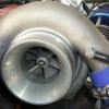
You can adjust your boost by that black thing you are holding in the picture above.

It should have a screw or maybe the whole thing itself can turn.

Turn it anti clockwise which should turn the boost down

Repeat and test

  • Replies 48
  • Created
  • Last Reply

Top Posters In This Topic

I looked at that Controller and it has no screw in it, but i can see the thread :/

im a bit lost to where my problem would be, can i rule anything out like AFM, pod filter?

http://i1272.photobucket.com/albums/y396/Adrian701/IMG_0140_zps511f9081.jpg - what about these nipples, clearly their are hoses missing off them, and that bolt i found in the pipe nipple kinda puts me off..

Where would i go from here, thank you!

I looked at that Controller and it has no screw in it, but i can see the thread :/

im a bit lost to where my problem would be, can i rule anything out like AFM, pod filter?

http://i1272.photobu...zps511f9081.jpg - what about these nipples, clearly their are hoses missing off them, and that bolt i found in the pipe nipple kinda puts me off..

Where would i go from here, thank you!

Only way you can rule out the AFM or Pod is by replacing them with another working item.

As I said I can pretty much be 95% sure its going to be the rev limited of a faulty AFM.

Does unplugging you AFM change anything?

unplugging the AFM will make the idle horrible, so i need to get my hands on another pink label AFM? it needs to go regardless since the top mounting flange on it is snapped.. Should i worry about the hoses? if they are in the right place or not, how can i find out

unplugging the AFM will make the idle horrible, so i need to get my hands on another pink label AFM? it needs to go regardless since the top mounting flange on it is snapped.. Should i worry about the hoses? if they are in the right place or not, how can i find out

Hoses are fine.

When you rev the car to 3000rpm does it jolt and splutter or does it sound like the rev limiter?

You should get an AFM anyways as you said and that will possibly fix the problem.

It it doesnt then we can move onto other things such as changing spark plugs and testing coils.

i went for a drive again, and you can hear the car boost but its gutless, and sounds rough the whole car vibrates more then it should almost making a WRX sound when accelerating, the idle sound is still rough thats the best description i can give right now!

ill start looking around for an AFM, i really hope its only the AFM and nothing serious...

thanks for your input mate

that black bit is a GFB boost controller, should have a allen key screw in top.

screw it all way in till it just bottoms out, then wind out 3 turns, go for drive, adjust for desired boost.

i got one running 10psi, goes fine. cheap, but so was the car and its a weekend hack.

To be honest if it is happening around 3000-4000rpm and sounds like a rev limited.

If you find that it wont rev past that point then its 95% of the time your AFM

Try using a friends to test this.

But my friend just had this exact problem with it only reving to 3000-4000rpm and then would limiter bash.

It turns out his AFM was not plugged in

I might also add that it could be hitting boost cut.

You can adjust your boost by that black thing you are holding in the picture above.

It should have a screw or maybe the whole thing itself can turn.

Turn it anti clockwise which should turn the boost down

Repeat and test

well whats happened to the stock boost feed from the compressor cover then?? im confused why the boost is fed from that t section...

how could it be a rev limiter cut? hes got a stock ecu doesnt he??? he'd need atleast a power fc to implement a rev cut?

what boost cut are you talking about, i have a s2 and when i had stock computer with high flow there was no such thing, it just boosted up and up and up so im confused here... i think he should just connect the stock setup like it would be stock, and replace afm and connect filter again ...

If your after an afm i have one sitting on my desk here that no one would buy, if you pay for postage its yours...its mint

Edited by SliverS2

Silver go turn your boost up and see what the stock ECU does without nistune. It revs hard and then cuts like a massive jolt.

Or go unplug your AFM and notice how the car won't rev past 4K it's a safety feature built into the stock ECU to make sure it won't do much damage when it doesn't know the air to fuel ratios.

The aftermarket boost controller connects to a boost source most probably on the intercooler pipe and then into the actuator.

On the stock setup it also has a line going to the intake from what I remember and this is blocked using a screw or in the case of an aftermarket intake it's non existent.

No offense bro but maybe you shouldn't be giving advice if you can't spot an aftermarket boost controller setup

SilverS2, pm'd

thanks for everything guys, ive ordered a few parts, a new K&N apollo pod filter, ARK Design Boost Controller, and a Turbosmart Boost gauge, which should be here next week, i take it that ill have to return the standard setup when i take out that GFB boost controller?

No. If you're taking out the little GFB controller to put the new one in, then just install the new one according to either its instructions or common sense (depending on which makes the most sense!). There's only 2 main connections to teh car. 1) The boost sense source (off the compressor housing or the intercooler pipe) and 2) the actuator. It's difficult to make a proper mistake.

Silver go turn your boost up and see what the stock ECU does without nistune. It revs hard and then cuts like a massive jolt.

Or go unplug your AFM and notice how the car won't rev past 4K it's a safety feature built into the stock ECU to make sure it won't do much damage when it doesn't know the air to fuel ratios.

The aftermarket boost controller connects to a boost source most probably on the intercooler pipe and then into the actuator.

On the stock setup it also has a line going to the intake from what I remember and this is blocked using a screw or in the case of an aftermarket intake it's non existent.

No offense bro but maybe you shouldn't be giving advice if you can't spot an aftermarket boost controller setup

Kasko- i used to have a stock computer and it allowed alot of boost with none the the jolting cuts, it just lost alot of power , you have a series 1 and he has a series 2, thats why i thought id comment, no offense taken. :) Im sure theres good reason to take the boost reading from the comp cover or close by, taking it from the manifold cant be right, what about the pressure drop thru the intercooler,

Edited by SliverS2

While we are talking about boost controllers, I have a turbosmart boost tee connected to the plenum. It is normal for them to bleed air at idle from the little port on the side yeah? Or is this why you say connect it to a pressure source?

Also since I fitted my ATR43G3 last week I have noticed that manifold vacuum has dropped from ~24inhg to 20inhg. I made up a 4" intake and after I reinstalled noticed I had an extra vacuum line that I totally forgot where it goes. Stuck a bolt in it for now, it comes from the t piece that supplies the wastegate actuator. Anyone got any idea where that is meant to go?

Create an account or sign in to comment

You need to be a member in order to leave a comment

Create an account

Sign up for a new account in our community. It's easy!

Register a new account

Sign in

Already have an account? Sign in here.

Sign In Now


  • Similar Content

  • Latest Posts

    • For once a good news  It needed to be adjusted by that one nut and it is ok  At least something was easy But thank you very much for help. But a small issue is now(gearbox) that when the car is stationary you can hear "clinking" from gearbox so some of the bearing is 100% not that happy... It goes away once you push clutch so it is 100% gearbox. Just if you know...what that bearing could be? It sounding like "spun bearing" but it is louder.
    • Yeah, that's fine**. But the numbers you came up with are just wrong. Try it for yourself. Put in any voltage from the possible range and see what result you get. You get nonsense. ** When I say "fine", I mean, it's still shit. The very simple linear formula (slope & intercept) is shit for a sensor with a non-linear response. This is the curve, from your data above. Look at the CURVE! It's only really linear between about 30 and 90 °C. And if you used only that range to define a curve, it would be great. But you would go more and more wrong as you went to higher temps. And that is why the slope & intercept found when you use 50 and 150 as the end points is so bad halfway between those points. The real curve is a long way below the linear curve which just zips straight between the end points, like this one. You could probably use the same slope and a lower intercept, to move that straight line down, and spread the error out. But you would 5-10°C off in a lot of places. You'd need to say what temperature range you really wanted to be most right - say, 100 to 130, and plop the line closest to teh real curve in that region, which would make it quite wrong down at the lower temperatures. Let me just say that HPTuners are not being realistic in only allowing for a simple linear curve. 
    • I feel I should re-iterate. The above picture is the only option available in the software and the blurb from HP Tuners I quoted earlier is the only way to add data to it and that's the description they offer as to how to figure it out. The only fields available is the blank box after (Input/ ) and the box right before = Output. Those are the only numbers that can be entered.
    • No, your formula is arse backwards. Mine is totally different to yours, and is the one I said was bang on at 50 and 150. I'll put your data into Excel (actually it already is, chart it and fit a linear fit to it, aiming to make it evenly wrong across the whole span. But not now. Other things to do first.
    • God damnit. The only option I actually have in the software is the one that is screenshotted. I am glad that I at least got it right... for those two points. Would it actually change anything if I chose/used 80C and 120C as the two points instead? My brain wants to imagine the formula put into HPtuners would be the same equation, otherwise none of this makes sense to me, unless: 1) The formula you put into VCM Scanner/HPTuners is always linear 2) The two points/input pairs are only arbitrary to choose (as the documentation implies) IF the actual scaling of the sensor is linear. then 3) If the scaling is not linear, the two points you choose matter a great deal, because the formula will draw a line between those two points only.
×
×
  • Create New...