
How to change Nitrogen Accumulator Cannister - Attesa
Announcements
-
Similar Content
-
-
Latest Posts
-
 OK, Step 3, if you need to remove the valve body, either to replace it, the TCM, or to do a more complete drain. First, you need to disconnect the TCM input wires, they are about half way up the transmission on the drivers side. One plug and the wires are out of the way, but there is also a spring clip that stops the socket from sliding back into the transmission. On my car the spring clip was easy to get, but the socket was really stuck in the o-ring of the transmission housing and took some.....persuasion. You can see both the plug to remove (first) and the spring clip (second) in this pic Incidentally, right next to the plug, you can see where the casting has allowance for a dispstick/filler which Nissan decided not to provide. there is a cap held on with a 6mm head bolt that you can remove to overfill it (AMS recommend a 1.5l overfill). Final step before the big mess, remove the speed sensor that is clipped to the valve body at the rear of the box. Then removal of the Valve Body. For this the USDM Q50 workshop manual has a critical diagram: There are a billion bolts visible. Almost all of them do not need to be removed, just the 14 shown on the diagram. Even so, I both removed one extra, and didn't check which length bolt came from which location (more on that later....). Again it is worth undoing the 4 corners first, but leaving them a couple of turns in to hold the unit up....gravity is not your friend here and trans oil will be going everywhere. Once the corners are loose but still in remove all the other 10 bolts, then hold the valve body up with 1 hand while removing the final 4. Then, everything just comes free easily, or like in my case you start swearing because that plug is stuck in the casing. Done, the valve body and TCM are out
 -
OK, so if you are either going for the bigger fluid change or are changing the valve body which includes the Transmission Control Module (TCM), first you should have both a new gasket 31397-1XJ0A and a torque wrench that can work down to 8Nm (very low, probably a 1/4 drive one). You can probably get by without either, but I really didn't want to pull it all apart together due to a leak. First, you now need that big oil pan. The transmission pan is 450 long x 350 wide, and it will probably leak on all sides, so get ready for a mess. There are 24x 6mm headed bolts holding the pan on. I undid the 2 rear corners, then screwed those bolts back in a couple of turns to let the pan go low at that end, then removed all the middle bolts on each side. Then, undo the front corner bolts slowly while holding the pan up, and 80% of the fluid will head out the rear. From there, remove the remaining bolts and the pan is off. You can see it is still dripping oil absolutely everywhere...it dripped all night.... I got another couple of litres when I removed the pan, and then another few when I removed the valve body - all up another 4l on top of the 3 already dropped in step 1.
-
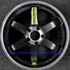
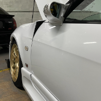
 Yeh I think i'll message an old contact i had for ages that manages his own tyre shop now.. n tell him what i want n work with him before ordering.. Got this 17x9 +30 Driftteks on 245/45/17 PSR Drag Radials on the rear.. They fit well - for your reference in future - Rear guards have been lipped in & minimal to non flaring of the rear Gaurds.
 -
 If only it were that easy! I also needed to remove seats, shocks, brake calipers, send my car through a fence, and use measuring and ended up guessing because I didn't remove seats, shocks and brake calipers. It can be hard sometimes Can be a little more complex than 'just measure' if you want to truly measure the entire wheel through all of it's suspension travel. But if you aren't going for every last mm then yeah, you can check the space you currently have and guesstimate.
 -
 If you own a car, and it has wheels on it, and you know the offset of those wheels, and you have a measuring device, you have everything you need to work out if other wheels will fit.
-


Recommended Posts
Create an account or sign in to comment
You need to be a member in order to leave a comment
Create an account
Sign up for a new account in our community. It's easy!
Register a new accountSign in
Already have an account? Sign in here.
Sign In Now