

Announcements
-
Similar Content
-
-
Latest Posts
-
 jeebus. glad you weren't under it while performing the stunt. Also thanks for the link to the wheel measurer, exactly what I needed
 -
In the older stuff there were very significant differences 2wd to 4wd, for example Stagea had strut front end for 2wd and double wishbone for 4wd so it was not minor to swap. From poking around the 2wd v37, it *looks* like it might be more possible; some of the parts specifically have "2wd" stamped on them which suggests the platforms are more similar. You'd still want to start with a 4wd half cut to swap stuff from though. I'd suggest if you don't have a tune on the ECU you don't really need one on the trans either. Throttle mapping is in the ECU side (and you can always use a Roar Pedal if you want the throttle to actually respond to your foot), and really if you are happy with the stock power you probably accept the stock trans behaviour too....its all made to be "sporty" not racey.
-
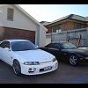
 So, updates. I have not washed the car since it came back from Tassie. I've driven it around a bit but not got around to actually sorting it out. I DID raise it because I cracked the rear bar leaving a hotel which was very distressing. Interestingly, the car drives more compliant now that it's raised a fair bit (5mm front, 15mm rear). Also noticed that my FR height was 10mm lower than FL. So that's now sorted out, too. I also bought this and had it printed: https://www.etsy.com/au/listing/1576422240/wheel-and-tire-fitment-tool-universal?ref=shop_home_feat_1&dd=1&logging_key=08f604d9fa4cc383550ba985e6ac85cd5cac7fbb%3A1576422240 Now, if I was smart I would have taken my brake calipers off to actually use this correctly but it was evident enough to me that in the region where the caliper was... there was nothing to hit suspension/guard/arm wise. So I'm going with "it'll be fine" after using the tool to hopefully very precisely measure the wheel clearance. Also while doing this, I had the very VERY bad idea of jacking one of the wheels/suspension arms up while the rest of the car was on jack stands. I did this to see how the arm would travel. This all was well and good until the car slid off the stands and went through a fence. So don't do that. Incredibly nobody was hurt and there was only minor damage to the rear bumper as the car didn't have far to slide, and had 3-4 wheels on it. The only damage turned out to be the fence itself which was easy to fix, and a little bit of damage to the fibreglass rear bumper trim. I had already planned to try a touch up paint kit to fix the time I drove into my garage door to see if it'd help in the interim before I get it fixed properly. I used the Dr Colorchip kit after looking online and seeing everyone talking about it. Yes it's made for chips and not huge broken missing pieces and I'll be 500% recommending it for stone chips after using it for stupid things like me. This took about ... 10 minutes and looking at the half assed photo the 30 second job I did on the bumper corner was almost perfect just by using the tiny little brush and painting it in. The sealact stuff to remove over-painting is really useful, so if/when I do it again I'll likely slather the touch up paint well over it and then clean it up with the cleaning solution. The wheels should arrive in a couple of weeks. I am still kinda confident after doing a stupid amount of measuring (and borrowing a set of 18x10.5+15) that they will not fit because I overlooked something, somehow and flew too close to the sun. ALSO R34 GTR guard liners do not fit on a GTT. I bought the undertray brake duct guides and had the wonderful problem of them not fitting my intake, my oil cooler and the liners themselves were even worse. Attempting to fit them won't work in general - You would have to cut them up as another poster mentioned as the bodywork is different on the GTT. At least I can try to resell them. So instead of cutting those up, I cut up my old already-cut-up GTT liners and extended them by using some PP plastic and drilling some 8mm holes for some nissan clips for the 'extra' bit. Because I was happy to cut them I was able to mount them pretty damn forward so I now have some semblance of guard liners, and the brake vents seal the bumper from the bottom. It sort-of-looks like this, to give some idea - If you look at the GTR and then the GTT this is when I realised that I needed to seriously measure as the inside of the rim area is entirely, entirely, entirely different and could not take any internet measurements for granted.
 -
 If you are Ecutek tuned then these TCU tunes are anywhere from $550 to $700 usd. If you are not ECUTEK tuned, then it gets costly!
 -
 Sorry to hear your HFM BM57 was faulty, did you contact HFM I would hope they would be at least grateful for the information if there was some sort of manufacturing fault, you would hope they would be sympathetic even if your item was 2 years old if it had never been fitted. May I ask where it leaked from ?
-


Recommended Posts
Create an account or sign in to comment
You need to be a member in order to leave a comment
Create an account
Sign up for a new account in our community. It's easy!
Register a new accountSign in
Already have an account? Sign in here.
Sign In Now