
Announcements
-
Similar Content
-
-
Latest Posts
-
 Dose will be able to confirm this more, but a 1.5 way IS a 2 way. It's just not as aggressive on one of the ramps. Changing from 2 to 1.5 I'm not sure how though.
 -
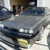
 No updates on the car but figured I'd share a nice outing. All the recent work paid off and I got it all together and out the shed for a car based pre-wedding celebration for a good mate of mine. Pretty casual cruise through the hills to a pub for lunch then out for some go-karting at The Bend. Headed down to Myponga for the night We stopped in at the reservoir before heading out down to the coast for lunch via the dam By the end of the weekend away I covered 350km and the 32 generally behaved its self. A good Shake down after being apart before the Track day in a few weeks
 -
 The front prop shaft from my GTR had very notchy unis, which obviously needed replacement but unfortunately uses the (usually) non-replaceable (staked) type. A new shaft is something like $2K plus shipping from Japan. I wouldn't even bother asking the local Nissan spares dept. Rang Hardy Spicer but no go, which surprised me a little. There's a place over Dandenong way that would make me a 'performance' shaft but un-necessary in my situation. They claimed to be getting the equipment in to replace staked unis but couldn't give me a timeframe. Anyway, long story short, found a place to do the work just 5 mins from me: https://knoxdriveshafts.com.au $420 (cash) and about a week later I have my driveshaft back. Price includes balancing. Owner is a one man band working out of a shed in his backyard but from what I could see he's very well setup with some expensive equipment.
 -
 Thanks. That's what I was after. One of the kits, the o-ring side is too big diameter. The other kit is a plate with a o-ring to seal and the hose connection offset.
 -

-


1.thumb.png.36afd656b26d55f5d425fc76e21561f2.png)


Recommended Posts
Create an account or sign in to comment
You need to be a member in order to leave a comment
Create an account
Sign up for a new account in our community. It's easy!
Register a new accountSign in
Already have an account? Sign in here.
Sign In Now