Jump to content
SAU Community

Recommended Posts

Thanks Geoff :blink: Like you said there are so many different ways it can be tackled.

Going into work tomorrow morning with everything to give it all a blast out and dry off before wrapping it all up in plastic film to bring home. From there i'll unwrap the parts as i need them and assemble it all. I used silicone on the oil pump last time, but even though i only used a smear it still over lapped the oil gallery hole slightly. Im thinking maybe to use a gasket but would prefer it if i didnt have to. If you use a gasket do you really just rely on the gasket doing all the sealing or do you still use a tiny bit of silicone? Looking for some input on which method to use.

Thanks everyone,

Deren

Deren, my preferred method is to use just a very thin film of blue gasket eliminator, so that it is not quite see through with no excess on the edges. I then take it up to firmly attached with the bolts, wait a while then put full bolt tension on.

Over the last couple of weeks i have throughly cleaned out and re-assembled the bottom end. As instructed, i used only WD40 in the bores and a smear of oil on the piston skirts. Im told this creates a very quick effiecent bed in of the rings instead of the first few cyles glazing over the oil. Anyway the whole bottom end is turning over very sweetly and im now satisfied i've done everything i can to provide me with many years of reliable, big power. After i torqued down the mains and big ends i fitted a new genuine water pump for reliable street and track use. I also refitted the crank baffle plates to the crank girdle.

Im about to order a Tomei sump baffle, Nismo engine mounts, and Cusco strut tops. While im waiting for the bits i will fit new bearings to the front diff and later fit the Tomei baffle and bolt up the sump. Im also currently ordering a Cometic metal head gasket, so once that arrives i can torque down the head.

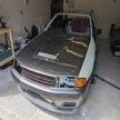
Heres some more pics.

post-14108-1190450561_thumb.jpg

post-14108-1190450637_thumb.jpg

post-14108-1190450762_thumb.jpg

post-14108-1190450839_thumb.jpg

Hey everyone. Small update. I've opted for a N1 oil pump as i can get a new one at a great price :down: Apparently not a huge benefit over stock apart from uprated flow and consequently pressure. So if anyone wants my stock RB26 oil pump feel free to take it off my hands!

Last night i made an order on Nengun for a Tomei sump baffle, Tomei metal head gasket and combination gaskets and Cusco pillowball front shocky upper mounts. I also ordered a new thermostat and oil pump gasket from nissan. So, slowly but surely i will get there!

Deren

Edited by Godzilla32

Deren you need some kids dude. That'd fix all these too-much-cash problems you've been having. Two is a good number to keep your bank balance nice and low. :)

PS Dude I'm moving to Forest Lake at the end of the year. Is that anywhere near you? I still want to see your beast in the flesh. :blink:

Deren you need some kids dude. That'd fix all these too-much-cash problems you've been having. Two is a good number to keep your bank balance nice and low. :worship:

PS Dude I'm moving to Forest Lake at the end of the year. Is that anywhere near you? I still want to see your beast in the flesh. :(

Hey mate, Im an apprentice mechanic so i can assure you i do not have too much cash lol. I just spend every cent i earn on the car! In 6 weeks i'll have a baby boy :) I've heard the name forest lake but im not sure where it is. Be good to catch up!

Awesome work mate!!! Great to see you're restoring it to relatively stock performance. Cant wait to see it totally finished. It'll be a one of a kind 32 thats for sure.

I had planned to restore it to relative stock. However it'll now be good for upto 700hp. I have spent alot of cash on the bottom end. The rest of it has been quite well worked too. I have listed it all out a few times.

Deren

BTW n1 oil pump is less flow than stock not more - it is designed to lessen flow to the head at sustained high revs, the standard (and even the n1 pump to some extent) pumps too much oil to the head at high revs (thus all the oil control mods on built engines like external returns, restrictors on feeds and opening up oil returns.)

  • 2 weeks later...

Waiting on parts from Japan. Once they arrive i will bolt on and torque the head, bolt on the sump with the new tomei baffle fitted. Im having my throttle bodies re-done with oversize butterflies for a zero air leak, ultra low idle ;) Wont that be nice. Never screw around with GTR throttle bodies!! They will only ever cause you a headache after, trust me! Its not a cheap excersize to have them all recut either when there is six! Anyway i'll pick them up once they're done and i can afford them :( Then i've only gotta save up some more for my new Garrett's...and everything else :w00t:

  • 2 weeks later...

Hey everyone, just a quick update. I have been fitting a few bits and pieces over the last few days. Fitted my original oil pump as im told the N1 pumps are layered which leaves them more prone to cracking than the original item. The rest of the stuff i have been fiddling around with is just small things like the oil filter/heat exchanger housing, fitted a new genuine thermostat under a nicely polished housing, refitted the rear turbo oil return, etc.

The package from Japan should arrive this coming week so from there it'll be full steam ahead! :laugh:

Here are some new pics.

Deren

post-14108-1192882717_thumb.jpg

post-14108-1192882809_thumb.jpg

post-14108-1192882883_thumb.jpg

Hey all i have fitted up the heat exchanger and some of the heater/vacuum hose galleries its all pretty highly polished but the flash doesnt really do it justice. My order from Japan has been shipped now so it shouldnt be too much longer till it arrives..

Deren

post-14108-1193316248_thumb.jpg

post-14108-1193316428_thumb.jpg

post-14108-1193316576_thumb.jpg

post-14108-1193316652_thumb.jpg

Hey mate

This has come a LONG way since my last post :P

Did you end up getting the new trim parts from nissan? Im about to do the interior on mine, the rear quarter surrounds are looking fairly average, and the handbrake is a bit more "used" than id like

yeah i was thinking about buying a new handbrake too.

I bought a brand new r34 gtt one when I did the stagea manual conversion and it looks great (and not too pricey). wonder if they have r32 ones still in stock

/goes off to order one before either of you....

Create an account or sign in to comment

You need to be a member in order to leave a comment

Create an account

Sign up for a new account in our community. It's easy!

Register a new account

Sign in

Already have an account? Sign in here.

Sign In Now


  • Similar Content

  • Latest Posts

    • When I said "wiring diagram", I meant the car's wiring diagram. You need to understand how and when 12V appears on certain wires/terminals, when 0V is allowed to appear on certain wires/terminals (which is the difference between supply side switching, and earth side switching), for the way that the car is supposed to work without the immobiliser. Then you start looking for those voltages in the appropriate places at the appropriate times (ie, relay terminals, ECU terminals, fuel pump terminals, at different ignition switch positions, and at times such as "immediately after switching to ON" and "say, 5-10s after switching to ON". You will find that you are not getting what you need when and where you need it, and because you understand what you need and when, from working through the wiring diagram, you can then likely work out why you're not getting it. And that will lead you to the mess that has been made of the associated wires around the immobiliser. But seriously, there is no way that we will be able to find or lead you to the fault from here. You will have to do it at the car, because it will be something f**ked up, and there are a near infinite number of ways for it to be f**ked up. The wiring diagram will give you wire colours and pin numbers and so you can do continuity testing and voltage/time probing and start to work out what is right and what is wrong. I can only close my eyes and imagine a rat's nest of wiring under the dash. You can actually see and touch it.
    • So I found this: https://www.efihardware.com/temperature-sensor-voltage-calculator I didn't know what the pullup resistor is. So I thought if I used my table of known values I could estimate it by putting a value into the pullup resistor, and this should line up with the voltages I had measured. Eventually I got this table out of it by using 210ohms as the pullup resistor. 180C 0.232V - Predicted 175C 0.254V - Predicted 170C 0.278V - Predicted 165C 0.305V - Predicted 160C 0.336V - Predicted 155C 0.369V - Predicted 150C 0.407V - Predicted 145C 0.448V - Predicted 140C 0.494V - Predicted 135C 0.545V - Predicted 130C 0.603V - Predicted 125C 0.668V - Predicted 120C 0.740V - Predicted 115C 0.817V - Predicted 110C 0.914V - Predicted 105C 1.023V - Predicted 100C 1.15V 90C 1.42V - Predicted 85C 1.59V 80C 1.74V 75C 1.94V 70C 2.10V 65C 2.33V 60C 2.56V 58C 2.68V 57C 2.70V 56C 2.74V 55C 2.78V 54C 2.80V 50C 2.98V 49C 3.06V 47C 3.18V 45C 3.23V 43C 3.36V 40C 3.51V 37C 3.67V 35C 3.75V 30C 4.00V As before, the formula in HPTuners is here: https://www.hptuners.com/documentation/files/VCM-Scanner/Content/vcm_scanner/defining_a_transform.htm?Highlight=defining a transform Specifically: In my case I used 50C and 150C, given the sensor is supposedly for that. Input 1 = 2.98V Output 1 = 50C Input 2 = 0.407V Output 2 = 150C (0.407-2.98) / (150-50) -2.573/100 = -0.02573 2.98/-0.02573 + 47.045 = 50 So the corresponding formula should be: (Input / -0.02573) + 47.045 = Output.   If someone can confirm my math it'd be great. Supposedly you can pick any two pairs of the data to make this formula.
    • Well this shows me the fuel pump relay is inside the base of the drivers A Pillar, and goes into the main power wire, and it connects to the ignition. The alarm is.... in the base of the drivers A Pillar. The issue is that I'm not getting 12v to the pump at ignition which tells me that relay isn't being triggered. AVS told me the immobiliser should be open until the ignition is active. So once ignition is active, the immobiliser relay should be telling that fuel pump relay to close which completes the circuit. But I'm not getting voltage at the relay in the rear triggered by the ECU, which leaves me back at the same assumption that that relay was never connected into the immobiliser. This is what I'm trying to verify, that my assumption is the most likely scenario and I'll go back to the alarm tech yet again that he needs to fix his work.      Here is the alarms wiring diagram, so my assumption is IM3A, IM3B, or both, aren't connected or improper. But this is all sealed up, with black wiring, and loomed  
    • Ceste, jak se mas Marek...sorry I only have english keyboard. Are you a fan of Poland's greatest band ever?   
×
×
  • Create New...