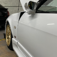
Stupid Attesa!
Announcements
-
Similar Content
-
Latest Posts
-
I'm going to slap an old nismo logo sticker on my spare one and sell it to the land of the free for a thousand bucks
-
Well - they have arrived. And they are easy on the eye to put it mildly... These only have three bolts - but for a start there is a key that fits with vacuum like precision.. And as you can see by my ruler, the interface is large.. I listened to a podcast on HP Academy about Dan (KiwiCNC) and I'm more than comfortable he knows what he is doing. R35 Bearing assembly should arrive later today so can mock that up for a look. Can't wait to get these on and get some brake pressure logging too. IMG_3860.MP4
-
I would be very confident that they are the same parts (the 2 different SKUs). It seems very clear that you can drop the cam in the 2-way opening, or in the other opening. If you arrange it in the other opening in the same way that you see any other 1-way diff, ie, with the flat of the cam up against the 1° side of the opening, then it would work as a 1-way. It can only spread the ramps when driving forwards - cannot spread the ramps on overrun. It would then appear obvious that if you put the cam into the opening "backwards", that you would get the angled flats of the cam working onto the "points" of the 1° side of the opening, which would give you ramp spread in both loading directions. I do wonder if the forward direction of the 1.5-way config is equivalent to the forward direction of the 2-way, seeing as the cams are flipped and the angled surfaces on those would need to be the same on each side - AND - clearly when installed in either the 2-way or 1-1ay configuration they are not intended to work exactly the same (the ramp angles on the 2-way are 10° different between forward and backward, and the ramp doesn't exist in the 1-way config). 'twere me, I think I would rather actually have a set of rings that offered the 2-way with two different sets of ramp angles, say the 55/45 of the existing design and maybe a 45/37.5 combo for a less aggressive effect), AND another set of rings with a dedicated 1.5-way opening and a dedicated 1-way opening. The 1.5-way opening would actually have the steeper angle on the overdrive side that causes it to be less pushy than the forward drive angle, like you see in many other diffs. But really - if this Nismo thing is thought out properly and all those surfaces work on each other the way that they need to, who am I to argue?
-


Recommended Posts
Create an account or sign in to comment
You need to be a member in order to leave a comment
Create an account
Sign up for a new account in our community. It's easy!
Register a new accountSign in
Already have an account? Sign in here.
Sign In Now