Jump to content
SAU Community

Recommended Posts

I was gonna add this on to someone else's old sub thread, but I thought I might make my own. Hope this is ok?

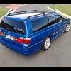
I recently purchased a 2000 rs stagea and found that the front speakers were blown. So that needed to be corrected. I am a little cheap so I was looking on ebay and wasn't having much luck. So I went to cash converters, which I never do. And found two new door speakers, and right next to it were two subs. So I grabbed them and an amp. And my project started.

I searched for a couple of boxes that would fit but couldn't find anything, so off to bunnings I went.

I wanted something cheap, but not crap.

So this is what I started with;

two (soon to be four) brand new sony xplod 200w 3-way 6.5" - rrp $70-80 got em for $25

two used (good cond) sony xplod 1000w sub's - rrp $120 each got em for $40 each

one used clarion apx4240 400w amp - rrp $290 got it for $45 (all after a bit of bartering with the manager ;-)

MDF- $23

Carpet- $19

glue & screws - $15

one cheap 12" box reatails at $70, dunno how much custom's would cost?

Total cost $197 and a weekend of my time

And I just used the Kenwood head unit that was in there, gonna upgrade to dvd/gps later.

So I wanted bass, but I also wanted space so this is what I decided on;

aV2lt_JA.jpg

got the design

gx1rdk4S.jpg

cut some mdf. I don't have a shed, so the lounge room had to suffice! I also don't have a jigsaw, so this was all cut by hand!

aV2luNCr.jpg

front top and bottom, no back for ventilation

aV2lvbyS.jpg

now as I wanted as much space as possible I decided to put the amp on the inside of the box, but it needed some ventalation. So I took the 12v exhaust fan off the power transformer of an old PC!

aV2lvFuA.jpg

Pq2nrhW0.jpg

cutting out the carpet

aV2lwOPJ.jpg

carpet glued on and sub in

aV2lx2NA.jpg

amp tucked in behind, tight fit!

Pq2ntbES.jpg

Pq2nwL8J.jpg

Pq2nxbAi.jpg

spaghetti time! There was a previous stereo install that had been removed, but unfortunately I couldn't use much of the left over spaghetti

Pq2nyuU0.jpg

spaghetti to the back

Pq2nyYPJ.jpg

spaghetti to the side

gx1rmZHJ.jpg

BYE BYE SPAGHETTI!

gx1rnsDr.jpg

NOw to neatly secure them using an L shaped bracket and the convienntly placed lug on the interior panel under th back window

gx1rokvA.jpg

gx1rouu9.jpg

gx1roLX9.jpg

The finished product

aV2lDvmS.jpg

Pq2nCxjA.jpg

just a few mill. clearence. Perfect.

Pq2nCOMA.jpg

and the same with the luggage cover

gx1rqUDS.jpg

Well that's the first project on my new car complete! Can't wait to do the next one.

Big thanks to alexcim for the stereo removal guide in the DIY section, and the SAU forum for all handy hints. Hope this might inspire/help someone else.

Let me know what you think,

Cheers,

Dave-

Edited by bayslideblue
Link to comment
https://www.sau.com.au/forums/topic/266175-stereo-install/
Share on other sites

Nice work mate, good design and tight fit!!

Unless there free air subs though u would need to have a back on the box as the sound waves coming from the back of the sub will cancel the ones from the front. The front and back need to be isolated from each other.

Link to comment
https://www.sau.com.au/forums/topic/266175-stereo-install/#findComment-4543578
Share on other sites

Unless there free air subs though u would need to have a back on the box as the sound waves coming from the back of the sub will cancel the ones from the front. The front and back need to be isolated from each other.

Hmm interesting I didn't know that. Do you think the fact that they are tight against the side wall would be enough?

Cheers

Link to comment
https://www.sau.com.au/forums/topic/266175-stereo-install/#findComment-4543585
Share on other sites

Hmm interesting I didn't know that. Do you think the fact that they are tight against the side wall would be enough?

Cheers

It will help that there tight as it would be stopping alot of it but if you sealed them u wud notice a huge difference.

For a temp measure you could jam the back of them full of dacron wadding, the filling they use in pillows, can but it from dress making shops.

Link to comment
https://www.sau.com.au/forums/topic/266175-stereo-install/#findComment-4543593
Share on other sites

WICKED JOB

i've always had this idea to put to 10inch subs behind the strut towers, but not covering the flaps on each side, just to get maximum space and access. but then i forgot i have to put amps some were and gave up on the idea lol.

and as Neil said about the air, picture this, my cousin made this setup in his Hq boot, completly air tight, the subs needed air to get the sounds out, so i guess the pressure from them blew out the key hole to the boot, and then it sounded alot better, so he had to cut holes in his parcel self to releave the pressure.

so yeah the air would escape around the tight fit on the side walls, unless the box itself is enclosed. you'll notice it

Link to comment
https://www.sau.com.au/forums/topic/266175-stereo-install/#findComment-4543599
Share on other sites

I am gonna ask the obvious question, how in the heck do you access the ATESSA bottle?

plus, further to what Neil was saying, they are NOT free to air subs (sony xplod dont make them), and there is no way there would be enough space in them boxes anyway. I would heartily recommend talking to your local stereo experts and getting some proper sizes for those sub boxes. It may just be a case of extending the faces out into the cargo area some more, but just remember that the size they give you (usually in m3 or litres) will not include the incursion of the speaker itself, or the volume taken up by the amp. Sounds like a lot of stuffing around, I know, but the difference in sound quality will amaze you.

double thumbs up for the effort you have gone to for a killer budget sound system though.

Link to comment
https://www.sau.com.au/forums/topic/266175-stereo-install/#findComment-4543823
Share on other sites

Nice work, looks the goods! :wacko:

the only thing is that your subs do not have the right amount of space (liter's) behind it.

my kenwood 12 inch subs need 25 liters of space each! (spare wheel out, subs in :D )

something you might want to think about if you want it to work and sound the way it should.

Link to comment
https://www.sau.com.au/forums/topic/266175-stereo-install/#findComment-4545209
Share on other sites

CHeers for the comments and the advice fella's-

I am gonna ask the obvious question, how in the heck do you access the ATESSA bottle?

plus, further to what Neil was saying, they are NOT free to air subs (sony xplod dont make them), and there is no way there would be enough space in them boxes anyway. I would heartily recommend talking to your local stereo experts and getting some proper sizes for those sub boxes. It may just be a case of extending the faces out into the cargo area some more, but just remember that the size they give you (usually in m3 or litres) will not include the incursion of the speaker itself, or the volume taken up by the amp. Sounds like a lot of stuffing around, I know, but the difference in sound quality will amaze you.

double thumbs up for the effort you have gone to for a killer budget sound system though.

Excuse me for being a complete noob, but what is the "ATESSA bottle" ?

As for making the boxes bigger to improve sound quality. Despite the fact that it's a pretty clear nice sounding system, after listening today I could gather that the potential of the subs is not being reached. So it may be worth my while as you say to extend the size of the boxes to the correct capacity. However I'm not sure if I wanna sacrifice the neat line that they sit in behind the strut tower.

Finding out exactly how much more room they need would be a good start though.

Thanks again,

Dave-

Link to comment
https://www.sau.com.au/forums/topic/266175-stereo-install/#findComment-4545242
Share on other sites

the fluid resovoir for the AWD system - its located behind the flap in the right hand side of the cargo area. If it runs dry of fluid and you get air in the system, hillarity will NOT ensue :woot:

Link to comment
https://www.sau.com.au/forums/topic/266175-stereo-install/#findComment-4545741
Share on other sites

the fluid resovoir for the AWD system - its located behind the flap in the right hand side of the cargo area. If it runs dry of fluid and you get air in the system, hillarity will NOT ensue :woot:

Assuming his car is AWD

His profile shows RS, ie RWD

Link to comment
https://www.sau.com.au/forums/topic/266175-stereo-install/#findComment-4546037
Share on other sites

Yeah Dale..........FAIL (I always wated to post that up, ha ha) He doesn't have an ATESSA system to worry about.

Great installation. You might consider putting some vents in the boxes. These would allow the air to move better.

I liked the way that you used the existing screw holes. All in all very neat, specially with limited tools.

Link to comment
https://www.sau.com.au/forums/topic/266175-stereo-install/#findComment-4546088
Share on other sites

Yeah Dale..........FAIL (I always wated to post that up, ha ha) He doesn't have an ATESSA system to worry about.

Great installation. You might consider putting some vents in the boxes. These would allow the air to move better.

I liked the way that you used the existing screw holes. All in all very neat, specially with limited tools.

Cheers mate!

Yeah I was wondering about what he meant by the ATESSA bottle, it's an rs. So yeah rwd, don't need to worry bout that.

There are vent holes in the top at the back, the amp side has an exhaust fan in it though.

I was wondering though some of the guys commenting further up said that you shouldn't let the sound waves from the back of the sub mix with those from the front. So I was wondering how do vents work with that theory?

Seems to work pretty well at the moment, the whole car vibrates with the bass :P . I might try some wadding in all the sides to make it completely air tight to see what the difference is though.

thanks again,

Dave-

Link to comment
https://www.sau.com.au/forums/topic/266175-stereo-install/#findComment-4547317
Share on other sites

Hey mate nice work on the install. Check out this Kicker site, it has lots of info that might help you understand just how subs and sub box's work. http://www.kicker.com/intro_to_enclosures there's even some info on that site on how to design different type's of box's.

Edited by DSTROY
Link to comment
https://www.sau.com.au/forums/topic/266175-stereo-install/#findComment-4549850
Share on other sites

Hey mate nice work on the install. Check out this Kicker site, it has lots of info that might help you understand just how subs and sub box's work. http://www.kicker.com/intro_to_enclosures there's even some info on that site on how to design different type's of box's.

Cool cheers mate, was a good read. probably should have read something like that before doing the install :D . My vents will not be working efficiently as they are not quite far enough away from the wall.

As for for there being no back on the box's it won't cancel out, if it's not air tight it will just not resonate properly (from what I can gather).

It states in that doc that noise cancelling only occurs with free air subs.

Which mine aren't, so should be right there.

As for having the right amount of space I did a rough estimate of the total air space within the box and came up with 30.15 litre's. That's not minus the sub or the sub and amp on the amp side. But i would imagine that on the side without the amp it would have at least 25lt of air space, which should be sufficient going by nismor32's recomendations for his 12"s.

However on the side with the amp and wiring in it I would imagine that it would come under that mark.

I don't think that it's enough to make me chage the size of the box though, it still seems pretty close to optimal but not perfect. Which is ok with me.

THanks for the help

:)

Link to comment
https://www.sau.com.au/forums/topic/266175-stereo-install/#findComment-4550012
Share on other sites

Create an account or sign in to comment

You need to be a member in order to leave a comment

Create an account

Sign up for a new account in our community. It's easy!

Register a new account

Sign in

Already have an account? Sign in here.

Sign In Now


  • Similar Content

  • Latest Posts

    • Well, that's kinda the point. The calipers might interfere with the inside of the barrels 16" rims are only about 14" inside the barrels, which is ~350mm, and 334mm rotors only leave about 8mm outboard for the caliper before you get to 350, And.... that;s not gunna be enough. If the rims have a larger ID than that, you might sneak it in. I'd be putting a measuring stick inside the wheel and eyeballing the extra required for the caliper outboard of the rotor before committing to bolting it all on.
    • OK, so again it has been a bit of a break but it was around researching what had been done since I didn't have access to Neil's records and not everything is obvious without pulling stuff apart. Happily the guy who assembled the engine had kept reasonable records, so we now know the final spec is: Bottom end: Standard block and crank Ross 86.5mm forgies, 9:1 compression Spool forged rods Standard main bolts Oil pump Spool billet gears in standard housing Aeroflow extended and baffled sump Head Freshly rebuilt standard head with new 80lb valve springs Mild porting/port match Head oil feed restrictor VCT disabled Tighe 805C reground cams (255 duration, 8.93 lift)  Adjustable cam gears on inlet/exhaust Standard head bolts, gasket not confirmed but assumed MLS External 555cc Nismo injectors Z32 AFM Bosch 023 Intank fuel pump Garret 2871 (factory housings and manifold) Hypertune FFP plenum with standard throttle   Time to book in a trip to Unigroup
    • I forgot about my shiny new plates!
    • Well, apparently they do fit, however this wont be a problem if not because the car will be stationary while i do the suspension work. I was just going to use the 16's to roll the old girl around if I needed to. I just need to get the E90 back on the road first. Yes! I'm a believer! 🙌 So, I contacted them because the site kinda sucks and I was really confused about what I'd need. They put together a package for me and because I was spraying all the seat surfaces and not doing spot fixes I decided not to send them a headrest to colour match, I just used their colour on file (and it was spot on).  I got some heavy duty cleaner, 1L of colour, a small bottle of dye hardener and a small bottle of the dye top coat. I also got a spray gun as I needed a larger nozzle than the gun I had and it was only $40 extra. From memory the total was ~$450 ish. Its not cheap but the result is awesome. They did add repair bits and pieces to the quote originally and the cost came down significantly when I said I didn't need any repair products. I did it over a weekend. The only issues I had were my own; I forgot to mix the hardener into the dye two coats but I had enough dye for 2 more coats with the hardener. I also just used up all the dye because why not and i rushed the last coat which gave me some runs. Thankfully the runs are under the headrests. The gun pattern wasn't great, very round and would have been better if it was a line. It made it a little tricky to get consistent coverage and I think having done the extra coats probably helped conceal any coverage issues. I contacted them again a few months later so I could get our X5 done (who the f**k thought white leather was a good idea for a family car?!) and they said they had some training to do in Sydney and I could get a reduced rate on the leather fix in the X5 if I let them demo their product on our car. So I agreed. When I took Bec in the E39 to pick it up, I showed them the job I'd done in my car and they were all (students included) really impressed. Note that they said the runs I created could be fixed easily at the time with a brush or an air compressor gun. So, now with the two cars done I can absolutely recommend Colourlock.  I'll take pics of both interiors and create a new thread.
    • Power is fed to the ECU when the ignition switch is switched to IGN, at terminal 58. That same wire also connects to the ECCS relay to provide both the coil power and the contact side. When the ECU sees power at 58 it switches 16 to earth, which pulls the ECCS relay on, which feeds main power into the ECU and also to a bunch of other things. None of this is directly involved in the fuel pump - it just has to happen first. The ECU will pull terminal 18 to earth when it wants the fuel pump to run. This allows the fuel pump relay to pull in, which switches power on into the rest of the fuel pump control equipment. The fuel pump control regulator is controlled from terminal 104 on the ECU and is switched high or low depending on whether the ECU thinks the pump needs to run high or low. (I don't know which way around that is, and it really doesn't matter right now). The fuel pump control reg is really just a resistor that controls how the power through the pump goes to earth. Either straight to earth, or via the resistor. This part doesn't matter much to us today. The power to the fuel pump relay comes from one of the switched wires from the IGN switch and fusebox that is not shown off to the left of this page. That power runs the fuel pump relay coil and a number of other engine peripherals. Those peripherals don't really matter. All that matters is that there should be power available at the relay when the key is in the right position. At least - I think it's switched. If it's not switched, then power will be there all the time. Either way, if you don't have power there when you need it (ie, key on) then it won't work. The input-output switching side of the relay gains its power from a line similar (but not the same as) the one that feeds the ECU. SO I presume that is switched. Again, if there is not power there when you need it, then you have to look upstream. And... the upshot of all that? There is no "ground" at the fuel pump relay. Where you say: and say that pin 1 Black/Pink is ground, that is not true. The ECU trigger is AF73, is black/pink, and is the "ground". When the ECU says it is. The Blue/White wire is the "constant" 12V to power the relay's coil. And when I say "constant", I mean it may well only be on when the key is on. As I said above. So, when the ECU says not to be running the pump (which is any time after about 3s of switching on, with no crank signal or engine speed yet), then you should see 12V at both 1 and 2. Because the 12V will be all the way up to the ECU terminal 18, waiting to be switched to ground. When the ECU switches the fuel pump on, then AF73 should go to ~0V, having been switched to ground and the voltage drop now occurring over the relay coil. 3 & 5 are easy. 5 is the other "constant" 12V, that may or may not be constant but will very much want to be there when the key is on. Same as above. 3 goes to the pump. There should never be 12V visible at 3 unless the relay is pulled in. As to where the immobiliser might have been spliced into all this.... It will either have to be on wire AF70 or AF71, whichever is most accessible near the alarm. Given that all those wires run from the engine bay fusebox or the ECU, via the driver's area to the rear of the car, it could really be either. AF70 will be the same colour from the appropriate fuse all the way to the pump. If it has been cut and is dangling, you should be able to see that  in that area somewhere. Same with AF71.   You really should be able to force the pump to run. Just jump 12V onto AF72 and it should go. That will prove that the pump itself is willing to go along with you when you sort out the upstream. You really should be able to force the fuel pump relay on. Just short AF73 to earth when the key is on. If the pump runs, then the relay is fine, and all the power up to both inputs on the relay is fine. If it doesn't run (and given that you checked the relay itself actually works) then one or both of AF70 and AF71 are not bringing power to the game.
×
×
  • Create New...