
Announcements
-
Similar Content
-
-
Latest Posts
-
 Interesting. I still think they are the result of impact damage somewhere along the line, but clearly lightning has stuck thrice! I've still got the original ones on my race car and they have had some hard work.
 -
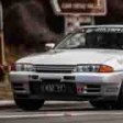 Just had this happen to me too. R32 GTR. Also broke "just before going out onto the track" - someone up there is looking out for us... Very scary since I was about to do a narrow street course with zero run-off and curbs everywhere. Many people on here upgrading to billet uprights and R35 bearings? Or buying new OEM knuckles? I am not keen to replace with another s/h 30 year old fatigued part.
 -

By joshuaho96 · Posted
Top off with distilled water and see what happens. If you keep losing coolant then you know to start looking. -

By Murray_Calavera · Posted
Nope. Grab a varex and turn it down as you get close to home, win win? -
 So, I've had my V36 for about a month now and have already copped an "excessive exhaust noise" notification from QLD TMR, reported by someone in my local area. It's a twin as per the original, and can have a bit of a throaty note to it when idling cold 😄 and if I do get up it a bit, it can be noisy, but it did pass a roadworthy inspection before sale, so.... ... but in the interest of being a good neighbour, I do want to quieten it down a bit. Is anyone here running a quiet aftermarket cat-back on their V36 or 370Z? And the big, bold question: does an aftermarket cat-back really make much of a performance difference on these cars?
-


1.thumb.png.36afd656b26d55f5d425fc76e21561f2.png)

Recommended Posts
Create an account or sign in to comment
You need to be a member in order to leave a comment
Create an account
Sign up for a new account in our community. It's easy!
Register a new accountSign in
Already have an account? Sign in here.
Sign In Now