
Announcements
-
Similar Content
-
-
Latest Posts
-
 About $4k brand new, available from vendors in Oz, or via an importer from Japan. Although that is for an R34 box, so you also need to buy the push clutch front plate (brand new from Nissan) and swap that over, and drill the bellhousing for a push clutch slave cylinder.
 -
By nouveau_poor · Posted
Absolutely could be. I collected data logs from when the O2 sensor was still out and also after I had replaced it so will try to compare them. Pretty confident that the affect is lowered with the new sensor, will check logs at the same RPMs/conditions. -
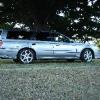
 Hey guys Long time lurker, I daily a nm35 stagea 250t rs four and I've had it for almost 2 years (very reliable 👌). Issues or just looking for information ill always find myself here having a read, so thought id join. 3inch stainless intake, pod filter, AM performance turbo dump pipe, 3inch hotdog, 3 and half inch stainless to 3 and half inch AM performance blast pipes. Bc racing coilovers. 18inch rims Hdi intercooler and trans cooler soon. Here's my car
 -
 thanks for the advice on the box... i was thinking the 6 speed was better for cruising on the highway but on closer inspection and comparison the Rb 5 speed box was not too different... So the choice is going to be the RB25 box... if I can save up and find one at the right price
 -
Thanks Matt, yes that's what i am aiming for. Just going to apply the right voltage and grounds to the dash connector. Hence my search for these pins... any chance you know if these pins are in the same spot as the ones on the S15 Dash connector? as mentioned above on page 8?
-


Recommended Posts
Create an account or sign in to comment
You need to be a member in order to leave a comment
Create an account
Sign up for a new account in our community. It's easy!
Register a new accountSign in
Already have an account? Sign in here.
Sign In Now