

Announcements
-
Similar Content
-
-
Latest Posts
-
 Power steering is probably because someone has nuked the HICAS CU and you no longer have the variable power asist doing what it is supposed to. How much boost are you running? You are aware that any more than 10 psi on the stock ECU is just asking for it to go to full R&R (that's Rich & Retard, which is effectively Retarded and Retarded!) which kills all the power. Depending on the exact conditions, it can just be runnign on the fat and stupid end of the maps, then the conditions change, you make a little more boost and the ECU goes into panic.
 -
 @BuiltNotBought Just as GTSboy said. If you want driveabilty and more low down torque..keep the stock runners. They are VERY good from a factory. I have them too on my RB25DET NEO and as a GTSboy i have fmic but with stock piping route(i have Blitz intercooler) Iam making around 320 BHP and the car pulls "hard" from like 2,5k all the way to 7k. I have it dyno tuned to mimic N/A power curve and making little less max torque due to the smallbox tranny. But driveability is very great. I had 350Nm below 3k so car feels very quick.
 -
By MissMintyR33 · Posted
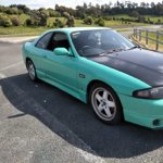
Looking to sort out a couple of issues on my skyline It recently was rebuilt, however rebuilder long story short did not give two flying effs about the work he did. So moving forward it's running but I have two persistent issues 1) it has a misfire / lag type of issue (was at higher RPMs but I had a dead piggy back ecu removed which improved it) now it's not as bad but still does it at random, I thought it may have been a boost issue I'm running an older turbosmart dual stage controller, turbosmart told me to try running off gate pressure however it still has a lag at random times. It has New MAF, maf plug, coil packs, sparks, CP harness.. injectors tested and cleaned. Factory ECU. 2) Power steering issue. It is tight as anything. Flushed power steering, rebuilt my pump because the bearing was shot. Flushed again still tight (mainly when parking and going slow into my driveway etc) No kinks in hard lines, replaced the lines I could see had cracks. Still tough to steer. I was told to shim a coin and place into the solenoid plug? Is there anything else. My steering angle sensor also has a issue. It's a used one I replaced, does it need to be calibrated? I feel like I've tried everything and this car is my voodoo doll. -

-
 One main filter. Each tank has a prefilter to keep rocks and small children out, then the big main filter that also does water separation. Clogged the first one so bad it was like a rev limiter at 3200rpm. Literally just like dropping the throttle off and maintaining rpm!
-


Recommended Posts