Jump to content
SAU Community

Recommended Posts

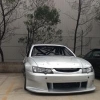
Thought id start a thread dedicated to chassis fabrication so people can gain ideas and inspiration from guys who have begun or completing extensive chassis works.

This is one of many cars thats being done recently in the workshop, by myeslf and a very experianced supertaxi fabricator

We started by cutting the entire front end off the car back to the front of the suspension towers

post-20349-0-26234000-1344743777_thumb.jpg

Reasons we leave the towers in, so we can use the strut top locations and work from them with the bar work. Even though we have moved the strut position for geometetry reasons its good to have the original location as a reference point.

post-20349-0-83552000-1344743801_thumb.jpg

post-20349-0-04967700-1344743816_thumb.jpg

post-20349-0-52325800-1344743826_thumb.jpg

post-20349-0-62870200-1344743838_thumb.jpg

Progress photos of the job. I new strut top has been fabricated as you can see.

The rails need to be reinforced at the support bars location but that is yet to change once the cage support bars are finalised.

Alot of people work from ideas with these types of jobs but we have done extensive design and FEA testing prior too cutting the strut tower out. Accurate measurements are taken then designs begin.

Here is a couiple of early renderings that were done. It can be seen the changes that have been made from these early drawings to what we are working from now.

post-20349-0-53586500-1344743848_thumb.jpg

post-20349-0-86465700-1344743864_thumb.jpg

After this job is complete we have a fairly extensive floorpan and cage to do in an R34 GTR.

post-20349-0-97595000-1344744308_thumb.jpg

post-20349-0-25192700-1344743790_thumb.jpg

Link to comment
https://www.sau.com.au/forums/topic/406830-chassis-fabrication-thread/
Share on other sites

Original cage was done about 4-5 years ago. Was a bonds kit that I installed way way back.

Alot of it is being removed and/or changed now to take the additional load of the strut towers.

The original dash bar was done using 1 3/4 tube which is fine but it's location isn't ideal anymore so its been relocated slightly now and tacked in, a couple of gussets and firewall diagonals will support it.

The car is also getting a tilton pedal box so the drivers side floor is also being braced and modified substantially.

The owner is rather tall so a supercar steering colum is being adapted so the seat can be pushed further back and the roof bars of the cage are being removed and replaced.

Here is something a little diffrerent

Its the rear subframe from a lotus exige/ellise

The faults from factory are that the lower toe arms are mounted using the same bolt and the rear lower control arm but they are single shear rod ends. The toe arm mounts at the back with the bolt going directly through the rod end.

We have converted the lower mount to a double shear pick up point to begin with.

The other issues are that the thin pressed galvinised subframe allows flex between the two lower points.

So weve fabricated a X section and lower support bar which is welded onto the pick up point and reinforced at the upper location with new plates welded in.

This is off the be blasted and powder coated this week, then we move on to the laser cut wing mounts and the bolt on alloy frame work to transfer the wings load directly onto this subframe

post-20349-0-70642500-1345368440_thumb.jpg

post-20349-0-39478000-1345368456_thumb.jpg

Create an account or sign in to comment

You need to be a member in order to leave a comment

Create an account

Sign up for a new account in our community. It's easy!

Register a new account

Sign in

Already have an account? Sign in here.

Sign In Now


  • Similar Content

  • Latest Posts

    • Lamb roast on Saturday will be different 🥲
    • They are under bucket shims. Tomei provides a test shim kit and then any measurement of shim required. 
    • I always wondered how you were supposed to buy a set of 24 buckets and somehow magically have every single one of them yield exactly the desired clearance. I would have thought you'd need to assemble a cam with either 12 "sample" or "example" buckets of known top thickness (or a single such sample/example 12 times over!!) measure clearances at every valve, and then do the usual math to work out what the actual "shimness" of each bucket needed to be, before buying the required buckets to make up he thicknesses that you didn't have on hand.
    • I now seem to be limited in power due to my rev limit/hydraulic lifters in my built RB25. I'm looking into converting over to Tomei solid lifters. Question for anyone that has done the conversion. I was always under the impression that when using the Tomei solid lifter conversion, you would also require new valves (Longer or shorter stems, I can't remember which).  I don't know where I got this idea, as so far I see no mention of this in any of the Tomei documentation. It just states I need the Tomei solid buckets, solid lifter cams and upgraded springs. As my head is already built, all I would need is another set of 1000$ Kelford cams, 500$ buckets and about 4H hours of my time installing and I'm off to the races!?!? There's no way it's that simple, I must be missing something? 
    • I couldn't agree more. I should have started from the get-go with a NEO or solid bucket conversion. I started looking into converting over to solid lifters yesterday. Now for some reason I was always under the impression that when using the Tomei solid lifter conversion, you would also require new valves (Longer or shorter stems, I can't remember which).  But I see no mention of this on any of the Tomei documentation. It just states that I need the Tomei solid buckets, solid lifter cams and upgraded springs. As my head is already built, all I would need is another set of 1000$ Kelford cams, 500$ buckets and about 4H hours of my time installing and I'm off to the races!?!? There's no way it's that simple, I must be missing something? 
×
×
  • Create New...