Jump to content
SAU Community

Recommended Posts

Hey guys, been ages since I've posted here but thought since I now own an RB powered vehicle I might as well start up again!

Well It's been a little while between imports, but this came up and couldn't refuse my love for it!

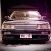
1989 Nissan C33 Laurel.

Picked it up with almost no brakes (foot park brake used to load onto trailer) and unknown condition of auto trans, as well as everything else without driving it. From what I inspected everything was ok except rocker cover gasket, steering rack leak and the obvious wear and tear.

smugshot4927288-L.jpg

smugshot6022901-L.jpg

First things first, bought a set of S13 front knuckles, calipers, hubs and discs. These were a little smaller then what was on it. I only needed rear discs but the S13 SR20DET discs did not fit. The rears had the drum park brake setup with 4 stud so assuming the same as R32/33 NA brakes. They still had minimum thickness pads so it was ok to last this week.

smugshot8361322-L.jpg

Then why waste time putting my old wheels on it!

smugshot6588884-L.jpg

smugshot6509016-L.jpg

smugshot4539661-L.jpg

smugshot489445-L.jpg

To pull it off I really need it super slammed, but with this exhaust I'm already having clearance issues on medium sized bumps :(

smugshot1527051-L.jpg

It currently has Tein coilovers and some form of a catback exhaust. HKS pod, Gates racing timing belt, and nothing else I've found yet. Sorry for a quick post but I'll upload a few more photos tonight and be sure to snap a few more this weekend on the hoist getting some TLC.

Not sure if its practical enough with the 15's, so considering a 5 stud swap for bigger brakes at the same time. If I go R33 gear, will I need a new coilover package? If I go S14, will the park brake cable need modification?

And if anyone has any RB20 manual swap stuff, or R32 handbrake setup available, let me know! I hate the foot park brake and auto!

Tom.

Link to comment
https://www.sau.com.au/forums/topic/411302-toms-c33-laurel/
Share on other sites

Looks sweet man.

Looks like you've got room to tuck your exhaust up a bit more/make a new one.

First thing I did with mine was swap the foot brake for a proper handbrake while maintaining the auto transmission. I found a C33 handbrake lever with the first part of the cable,and i had a manual centre console spare, you just need to make up some kind of spacer or bracket, because the lever doesnt bolt straight to the floorpan and needs about 20mm clearance.

General consensus is that R33s have the closest handbrake cable length, if you're trying to get the entire handbrake setup from another car.

For R33 brakes you'll need 16s, and nothing will need to be done about coilovers, etc.

Just put your 5 stud hubs on, cut the shroud and flare it back to accommodate the bigger rotor, and use a thin long screw or screw extractor to remove the olive fitting inside the calipers, so you can use your existing brake lines (which have provisions to clip into your coilovers)

Link to comment
https://www.sau.com.au/forums/topic/411302-toms-c33-laurel/#findComment-6574033
Share on other sites

Few more phots.

How I paid for the car (Beef Jerky included)

IMG9582-L.jpg

My mate came over on his Ruckus to give me a hand cleaning it up.

IMG9587-L.jpg

Yes, I am awaiting delivery for one of these bad boys!

IMG9588-L.jpg

Some of the crap I found in the boot.

IMG9586-L.jpg

JIC suspension receipt...obviously nto for this car since it has Teins.

IMG9589-L.jpg

Filthy engine bay.

IMG9592-L.jpg

The reason why I couldn't drive it home.

IMG9594-L.jpg

SSR's and my jealous mate.

IMG9595-L.jpg

IMG9598-L.jpg

Quite a lot of camber.

IMG9600-L.jpg

Balling interior, awaiting a boss kit for my wood grain Nardi.

IMG9604-L.jpg

Lowness/exhaust hang.

IMG9606-L.jpg

IMG9608-L.jpg

Gates racing.

IMG9609-L.jpg

Apexi spark plug.

IMG9613-L.jpg

Fixing up some rusted parts.

IMG9616-L.jpg

More photos this weekend!

Edited by Thomasino
  • Like 1
Link to comment
https://www.sau.com.au/forums/topic/411302-toms-c33-laurel/#findComment-6574988
Share on other sites

As Andrew r said, this is really tidy by the looks of the pics, I wish mine was that clean :(

As for rims, personally I think nt03s or rpf01s may look awkward on it, dunno why, maybe it's te shape of them but IMO they belong on more sports looking cars.

My ideal setup for wheels is what you have right now I think ssr mesh on c33s are porn! It just needs a little more low and I definitely think it pull them off really well.

Link to comment
https://www.sau.com.au/forums/topic/411302-toms-c33-laurel/#findComment-6578689
Share on other sites

Agree about the sporty look of RPF01's and NT03's on the luxury style car. Thinking maybe R33 GTR wheels or even R34. The brakes need an upgrade so considering s14/R33 combo.

And manual with HAND brake is definitely on the cards, already out of my mind driving it how it is! Interior has been swapped from the red velour and can't say if the leather/woodgrain is a standard option, maybe for the top of the line? Even has electric drivers seat! Not bad for 1989.

Exhaust definitely needs to be tucked/replaced, wouldn't mind a whole system but think a manual/handbrake comes first.

Quick photoshop with slammage and tint.

559652_10152177637740392_1840035933_n.jpg

JZX81 with R34 GTR's

kurumi3.jpg

JZX81 with R33 GTR's (it's ahrd to find C33 photos...)

20100122-01.JPG

I wouldn't mind getting some larger SSR's...

IMG_02241.jpg

Link to comment
https://www.sau.com.au/forums/topic/411302-toms-c33-laurel/#findComment-6584034
Share on other sites

yeah i agree on 33 gtrs, they look great on laurels, as would 34 gtrs.

As for sets of larger ssr mesh, i used to look alot on Yahoo JP, in 5 stud its so hard to find decent ssr mesh in good sizes, i think i found one pair of 16 x 9's +18 mint condition, had jesse streeter bid on them for me, won the auction, then the seller removed the highest bid (mine through jesse) and i missed out on them. Was devastated.

Apart from that most are shitty widths and offsets, and i think i've only seen one half decent pair in 17s

Link to comment
https://www.sau.com.au/forums/topic/411302-toms-c33-laurel/#findComment-6584116
Share on other sites

Create an account or sign in to comment

You need to be a member in order to leave a comment

Create an account

Sign up for a new account in our community. It's easy!

Register a new account

Sign in

Already have an account? Sign in here.

Sign In Now


  • Similar Content

  • Latest Posts

    • God damnit. The only option I actually have in the software is the one that is screenshotted. I am glad that I at least got it right... for those two points. Would it actually change anything if I chose/used 80C and 120C as the two points instead? My brain wants to imagine the formula put into HPtuners would be the same equation, otherwise none of this makes sense to me, unless: 1) The formula you put into VCM Scanner/HPTuners is always linear 2) The two points/input pairs are only arbitrary to choose (as the documentation implies) IF the actual scaling of the sensor is linear. then 3) If the scaling is not linear, the two points you choose matter a great deal, because the formula will draw a line between those two points only.
    • Nah, that is hella wrong. If I do a simple linear between 150°C (0.407v) and 50°C (2.98v) I get the formula Temperature = -38.8651*voltage + 165.8181 It is perfectly correct at 50 and 150, but it is as much as 20° out in the region of 110°C, because the actual data is significantly non-linear there. It is no more than 4° out down at the lowest temperatures, but is is seriously shit almost everywhere. I cannot believe that the instruction is to do a 2 point linear fit. I would say the method I used previously would have to be better.
    • When I said "wiring diagram", I meant the car's wiring diagram. You need to understand how and when 12V appears on certain wires/terminals, when 0V is allowed to appear on certain wires/terminals (which is the difference between supply side switching, and earth side switching), for the way that the car is supposed to work without the immobiliser. Then you start looking for those voltages in the appropriate places at the appropriate times (ie, relay terminals, ECU terminals, fuel pump terminals, at different ignition switch positions, and at times such as "immediately after switching to ON" and "say, 5-10s after switching to ON". You will find that you are not getting what you need when and where you need it, and because you understand what you need and when, from working through the wiring diagram, you can then likely work out why you're not getting it. And that will lead you to the mess that has been made of the associated wires around the immobiliser. But seriously, there is no way that we will be able to find or lead you to the fault from here. You will have to do it at the car, because it will be something f**ked up, and there are a near infinite number of ways for it to be f**ked up. The wiring diagram will give you wire colours and pin numbers and so you can do continuity testing and voltage/time probing and start to work out what is right and what is wrong. I can only close my eyes and imagine a rat's nest of wiring under the dash. You can actually see and touch it.
    • So I found this: https://www.efihardware.com/temperature-sensor-voltage-calculator I didn't know what the pullup resistor is. So I thought if I used my table of known values I could estimate it by putting a value into the pullup resistor, and this should line up with the voltages I had measured. Eventually I got this table out of it by using 210ohms as the pullup resistor. 180C 0.232V - Predicted 175C 0.254V - Predicted 170C 0.278V - Predicted 165C 0.305V - Predicted 160C 0.336V - Predicted 155C 0.369V - Predicted 150C 0.407V - Predicted 145C 0.448V - Predicted 140C 0.494V - Predicted 135C 0.545V - Predicted 130C 0.603V - Predicted 125C 0.668V - Predicted 120C 0.740V - Predicted 115C 0.817V - Predicted 110C 0.914V - Predicted 105C 1.023V - Predicted 100C 1.15V 90C 1.42V - Predicted 85C 1.59V 80C 1.74V 75C 1.94V 70C 2.10V 65C 2.33V 60C 2.56V 58C 2.68V 57C 2.70V 56C 2.74V 55C 2.78V 54C 2.80V 50C 2.98V 49C 3.06V 47C 3.18V 45C 3.23V 43C 3.36V 40C 3.51V 37C 3.67V 35C 3.75V 30C 4.00V As before, the formula in HPTuners is here: https://www.hptuners.com/documentation/files/VCM-Scanner/Content/vcm_scanner/defining_a_transform.htm?Highlight=defining a transform Specifically: In my case I used 50C and 150C, given the sensor is supposedly for that. Input 1 = 2.98V Output 1 = 50C Input 2 = 0.407V Output 2 = 150C (0.407-2.98) / (150-50) -2.573/100 = -0.02573 2.98/-0.02573 + 47.045 = 50 So the corresponding formula should be: (Input / -0.02573) + 47.045 = Output.   If someone can confirm my math it'd be great. Supposedly you can pick any two pairs of the data to make this formula.
×
×
  • Create New...