Jump to content
SAU Community

Recommended Posts

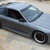
So a couple of guys in the Stagea subsection have asked me to post a build thread on my S15, being a non R31/2/3/4/5 and non RB i wasn't sure how it would go down but i have been assured it will be of interest to the community so here it is.

Purchased mechanically stock with typical retard mods of neons & clear tail lights - which were promptly removed/disabled (Not all bad however - came with a pretty decent $2000+ pro installed Alpine stereo).

Having modified a 200sx before (I had a S14a back in the 90’s) i had a fair idea of what i was after & how to achieve it – responsive usable power - so with this in mind i set about modifying.

Engine:

Camtech billet VCT Camshafts 260/260 10.5mm/10.5mm

Garrett GT28/71 52t - 400hp turbo

Speedflow oil / coolant lines

Sard 550cc Injectors

Z32 afm

Nistune ECU

Turbosmart plumb back BOV

Blitz Dual ID boost controller

3" exhaust

300x600x76 intercooler setup

Walbro fuel pump

wide band AFR meter

Oil catch can

k&N air filter

This combo ended up putting out 294rwhp / 220rwkw @ 16psi boost

Wheels:

Work Meister S1 3P - 18x8 & 18x9

Suspension:

HKS Hypermax III coil overs

Pics:

IMG_0152.jpg

IMG_0156.jpg

IMG_0459.jpg

IMG_0461.jpg

dynograph.jpg

  • Like 1
Link to comment
https://www.sau.com.au/forums/topic/415598-vq30det-s15-200sx-spec-r/
Share on other sites

So the SR20 was fantastic for a while, almost zero lag and a good street setup.

But I got bored, because my last car was this:

b7b869f8.jpg

c46f89ed.jpg

Which made 410rwkw.

So in a moment of weakness I bought one of these:

Cima%2520%25282%2529.JPG

Cima%2520%25283%2529.JPG

Cima%2520%25285%2529.JPG

Cima%2520%25281%2529.JPG

VQ30DET Y33 Cima front cut with a genuine 26,000km on the clock.

And then the conversion started.

First of all I sorted out the ECU, decided to go for a Nistune setup, as the car is a streetcar with A/C, P/S decided that the stock ECU modified would be the best plan.

After around 12 hours work using multiple wiring diagrams (removing body loom, airbag loom etc) , wiring = sorted

photo.jpg

Then had some of these made up so hold the engine and transmission in place:

IMG_8565.jpg

IMG_8567.jpg

Then SR20DET came out and real work started:

SR20DET and wiring loom came out and work started on installing new valve springs and 265 deg cams into the VQ30DET.

Anyways, pix of progress.

SR20 out - served me well, off to live a new life in a Datsun 200B coupe

IMAG0102.jpg

On trailer returning from engine & wiring loom removal

IMAG0104.jpg

Back home ready for work to commence

IMAG0110.jpg

IMAG0112.jpg

Drained motor of oil and cracked the sump, the motor was mint

IMAG0121.jpg

So then I decided that I wanted to chuck a set of cams in it.

All covers and accessories off and cams out - so much crap to come off to get the sticks out

IMAG0127.jpg

Jim Wolf spring compressor mocked up - fits up nicely.

IMAG0125.jpg

Valve springs all installed, cams are in & engine completely back together:

IMAG0135.jpg

IMAG0137.jpg

IMAG0142.jpg

IMAG0144.jpg

Also received my modified wiring loom back from being merged with the S15 engine / ABS loom – 100% plug in (with ABS, A/C, P/S and parts of the S15 body loom run as per OEM (ie, front left indicator))

IMAG0141.jpg

Then made a 350Z gearbox work with the VQ30DET

350Z gearshifter mounts way to far back to be used in an 'S' chassis car, to bring it back to a usable position I cut reshaped and rewelded the shifter base 80mm closer to the gearbox.

First job was to remove the gear shifter linkage and weld both ends together - basically removing the 80mm length as pictured in vice

IMAG0145.jpg

Then started on the shifter bracket. Drilled a series of holes in around the position i wanted to move the shifter base to.

IMAG0147.jpg

IMAG0148.jpg

Then removed the shifter base, file finished both shifter base and bracket then positioned everything where it needed to be and took to OKE020 to weld (cheers Scott).

And now all finished (minus reverse lockout plate).

IMAG0159.jpg

IMAG0161.jpg

(and a pic for comparison of standard location)

31d9471e.jpg

Then engine went in:

Tighter than a nuns nasty lowering it in but once on the mounts sits quite nicely.

Clutch and flywheel installed and box bolted on - ready for deployment.

IMAG0174.jpg

Early hours of engine installation

IMAG0176.jpg

And final resting position

IMAG0177.jpg

IMAG0180.jpg

IMAG0181.jpg

Rear of engine 80mm from firewall, front of engine 320mm to radiator support - with good clearance for all accessories around the engine

And finally, assembly !!

20121008_212741.jpg

20121008_212600.jpg

20121008_212934.jpg

20121008_213057.jpg

20121008_213348.jpg

Then made a box for the air filter:

20121028_214922.jpg

20121028_214655.jpg

20121028_215742.jpg

20121028_215823.jpg

20121029_195839.jpg

20121029_202530.jpg

20121029_202723.jpg

20121029_211224.jpg

And finally, running!!

Idle, 14.7:1 on the meter - loving those cams, sounds infinitely different than a stock cam VQ30 (230 deg Vs 265 & about another 1mm lift)

Oh yes the driveshaft, forgot about that -I had it made in Texas and shipped to Australia

Next piece of the puzzle complete - the tailshaft.

What a pain. Turns out an aftermarket 350Z slip yoke is almost unobtainum, even in the US - so an aftermarket tailshaft was going to be an interesting proposition.

Most guys solve this lack of aftermarket support by cutting the staked uni slip joint off a standard 350Z tailshaft - and try and find someone who will put it back together on a new shaft (which they shouldnt - one time use part).

Not particularly keen on this idea i went hunting....

After spending a number of weeks trawling the net for a better solution i stumbled across a drivshaft supplier in San Antonio Texas that claimed to build a aluminum tailshaft suit 350Z using all new parts.

We exchanged quite a few emails and they were happy to send me parts to have it all made here - but in the end decided to have it all made there as even with shipping included (which the driveshaft store organised, at a fairly substantial discount over retail) the shaft worked out at just over half the price of what it would cost to have made here, which seems freaking crazy being made half a world away ....but it still gets better.

I ordered and paid for the Driveshaft 8:30am Friday morning (Brisbane time) and arrived 9am the following wednesday - 3 business days to be custom made to my specs, balanced, packaged and sent half a world away - i dont think i could even have a drive shaft made locally and shipped in that kind of time.

So from San Antonio to Dallas then Kentucky, Honolulu, Tokyo, Sydney and finally onto Brisbane - it arrived, and here it is.

IMG_20120229_184519.jpg

IMG_20120229_185526.jpg

IMG_20120229_185559.jpg

IMG_20120229_192149.jpg

IMG_20120229_202005.jpg

Spec wise:

3.5" 6061 heavy duty aluminium tube (aluminium was selected due to length and critical RPM considerations)

32 spline 350Z slip yoke

Nissan R200 rear flange

spicer 1350 front uni

spicer 1310 rear uni

Edited by psi_999

And where i'm up to currently, i've just installed a header tank.

Top of the motor sits above the top of radiator so hoping to prevent cracked heads i fitted up a small header tank (which sits around 3 inches higher than the radiator).

20121209_144846.jpg

Now holds a perfect 88C :D

That tailshaft is a thing of beauty.

Love the fabrication work. :)

Cheers mate.

So much fabrication work around the bay, have tried to make it as hard to spot as possible.

ie, this is how the plenum had to be modified:

IMG_20120213_224858.jpg

IMG_20120213_224916.jpg

20120923_223232.jpg

And plenum ‘mid’ manifold was cut, milled flat and welded, needed around an inch out of it to allow the bonnet to close (no ugly bonnet bulges here).

IMG_20120218_125401.jpg

IMG_20120218_144722.jpg

IMG_20120218_182021.jpg

IMG_20120218_183630.jpg

IMG_20120218_192718.jpg

Whole build has been centered around shit looking as OEM as possible :)

Edited by psi_999

puts an engine in while wearing thongs...typical QLDer :laugh:

whats the turbo you mounted on there??

Yep, another boring Qld build LOL.

Turbo is a Brazilian Masterpower T70 (70mm compressor,' P' trim rear) - going to see how it tunes up and then decide if its hanging around long term.

No not tuned as yet, other than my amateur hour hack at the laptop LOL.

simpletool from here is going to have a crack at it in the next week or so, we are going to try and get a nice road tune (no boost) sorted before it gets sent to the tuner in the new year (PITS on the Gold Coast).

Will be interesting with 1000cc injectors, Ford racing lightning supercharged v8 MAF and 265 deg cams on Nistune.... see how we go i guess LOL.

It will love the boost. Don't be too scared to lean on it. If you upgraded the head studs while it was apart it would be good for 4-500kw, otherwise keep it around 300 or it will lift the head.

If the water temp rises too much on the dyno, contact me for one of my block coolant kits. I think it should work on the VQ30det. ;)

Hopefully it'll be strong enough, i'm only chasing 400rwhp:)

A mate has gone 10.7 @ 129 on a $300 motor, 22psi through a GT35 and 50hp N20, all stock unopened.

VQ's go alrite!!

Edited by psi_999

Create an account or sign in to comment

You need to be a member in order to leave a comment

Create an account

Sign up for a new account in our community. It's easy!

Register a new account

Sign in

Already have an account? Sign in here.

Sign In Now


  • Similar Content

  • Latest Posts

    • Did this end up working? Did you take some pictures?
    • And finally, the front lower mount. It was doubly weird. Firstly, the lower mount is held in with a bracket that has 3 bolts (it also acts as the steering lock stop), and then a nut on the shock lower mount itself. So, remove the 3x 14mm head bolts , then the 17mm nut that holds the shock in. From there, you can't actually remove the shock from the lower mount bolt (took me a while to work that out....) Sadly I don't have a pic of the other side, but the swaybar mounts to the same bolt that holds the shock in. You need to push that swaybar mount/bolt back so the shock can be pulled out past the lower control arm.  In this pic you can see the bolt partly pushed back, but it had to go further than that to release the shock. Once the shock is out, putting the new one in is "reverse of disassembly". Put the top of the shock through at least one hole and put a nut on loosely to hold it in place. Put the lower end in place and push the swaybar mount / shock bolt back in place, then loosely attach the other 2 top nuts. Bolt the bracket back in place with the 14mm head bolts and finally put the nut onto the lower bolt. Done....you have new suspension on your v37!
    • And now to the front.  No pics of the 3 nuts holding the front struts on, they are easy to spot. Undo 2 and leave the closest one on loosely. Underneath we have to deal with the wiring again, but this time its worse because the plug is behind the guard liner. You'll have to decide how much of the guard liner to remove, I undid the lower liner's top, inside and lower clips, but didn't pull it full off the guard. Same issue undoing the plug as at the rear, you need to firmly push the release clip from below while equally firmly gripping the plug body and pulling it out of  the socket. I used my fancy electrical disconnect pliers to get in there There is also one clip for the wiring, unlike at the rear I could not get behind it so just had to lever it up and out.....not in great condition to re-use in future.
    • Onto the rear lower shock mount. It's worth starting with a decent degrease to remove 10+ years of road grime, and perhaps also spray a penetrating oil on the shock lower nut. Don't forget to include the shock wiring and plug in the clean.... Deal with the wiring first; you need to release 2 clips where the wiring goes into the bracket (use long nose pliers behind the bracket to compress the clip so you can reuse it), and the rubber mount slides out, then release the plug.  I found it very hard to unplug, from underneath you can compress the tab with a screwdriver or similar, and gently but firmly pull the plug out of the socket (regular pliers may help but don't put too much pressure on the plastic. The lower mount is straightforward, 17mm nut and you can pull the shock out. As I wasn't putting a standard shock back in, I gave the car side wiring socket a generous gob of dialectric grease to keep crap out in the future. Putting the new shock in is straightforward, feed it into at least 1 of the bolt holes at the top and reach around to put a nut on it to hold it up. Then put on the other 2 top nuts loosely and put the shock onto the lower mounting bolt (you may need to lift the hub a little if the new shock is shorter). Tighten the lower nut and 3 upper nuts and you are done. In my case the BC Racing shocks came assembled for the fronts, but the rears needed to re-use the factory strut tops. For that you need spring compressors to take the pressure off the top nut (they are compressed enough when the spring can move between the top and bottom spring seats. Then a 17mm ring spanner to undo the nut while using an 8mm open spanner to stop the shaft turning (or, if you are really lucky you might get it off with a rattle gun).
    • You will now be able to lift the parcel shelf trim enough to get to the shock cover bolts; if you need to full remove the parcel shelf trim for some reason you also remove the escutcheons around the rear seat release and you will have to unplug the high stop light wiring from the boot. Next up is removal of the bracket; 6 nuts and a bolt Good news, you've finally got to the strut top! Remove the dust cover and the 3 shock mount nuts (perhaps leave 1 on lightly for now....) Same on the other side, but easier now you've done it all before
×
×
  • Create New...