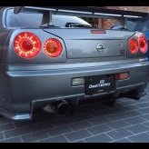
R34 Gtt - Steering Column/rod/rack Spacing Issue
Announcements
-
Similar Content
-
Latest Posts
-
By TurboTapin · Posted
For these last 7 years of ownership, I've always had to use a small scissor jack under one of the front tow hooks to raise the front just enough so my low-profile jack fits under to reach my subframe jack point. I'm beginning to get annoyed of always having to do this. Are there any lower low-profile jacks that fit under the gtr lip on a dropped car? -
Seat of the pants assessment of the new intake: The car is way less "doughy" when hitting the loud pedal, especially off idle when stopped or in traffic, I did use a cheapo lazer thermal thingo to measure the temp around where the pod filter got its air, it was between 55 - 60°C, in saying this the car was shut off and not moving, so the OEM intake pipe was not supplying any fresh air to where the pod was when the car was at least moving A weird bonus was induction noise on the throttle in the cabin increased a bit, I was worried that I was actually going to lose some of that induction noise I love so much, outside though, when I got the daughter to do a WOT drive by pass for me, the induction noise has increased alot when on the throttle, not quite ITB doort, but well up there I'm extremely happy with the results and have been exploring the country roads in the region As for house mods: 1.New front fence is up and is awesome, it really upgraded how the joint looks from the street, and the added security is nice 2. Electricians have replace some interior lights, and with more lighting in the garage, a few new motion detecting lights out the front above the garage, front room, and at the front door, which I have already found heaps helpful coming and going, also now has fancy pants CCTV all round the house The only hold point for power though is the solar and batteries due to supply issues, although this will happen over the next few weeks 3. I have done a heap of landscaping out the front and I'm almost ready to do a new small retaining wall with some nice blocks to replace the brick and cemented in rocks around the raised garden beds cemented in river stone "was the fashion at the time" the house was built. I currently have a pallet of retaining wall blocks and 2 bulka bags of 20mm blue metal to replace the wood chip that is in the raised garden beds around the house 4. I now have 3 big raised garden beds for out the back to grow some vegetables, about 70cm high, 200cm long and 100cm wide 5. My 2 compost bins are already pretty full with brown, green and kitchen waste from the landscaping I'vedone so far, but they will probably take a few months to break down, so anything else that gets chopped, trimmed, and kitchen waste will just start filling the base of the raised garden beds to about 30cm before I start throwing 40cm of good compost, and stuff, for the vegetables to grow in, I'll need a few ton of compost and soil, but the local supplier can sent me bulka bags of the stuff Basically the logs, wood chips and a few strategically placed rocks for drainage, will give the beds some good organic materials down low to break down over time, and they will hold moisture during the warmer months to save the water in my big arse water tank if we don't get alot of rain So, all in all, the car and house mods are going well, and I'm really enjoying being retired, I sleep in too 0700 and slowly plod around inside until I feel like actually doing anything, and only work in the yard for as long as want, which has actually been alot over the last few weeks, although when you look at it, it seems that not a huge amount of work has been done, until I look at the before I started the work pics Happy days and good times indeed
-
By DraftySquash · Posted
hahaha yeah. Plan is to get side skirts and probably just rear pods. But going to do them one-by-one. I've got a set that I really like from RHDJapen, but that one isn't shipped to AU. So need to find someone who can get it for me -
Here's an idea, answer the questions I asked you as they are trying to work out WHY the LSD will be binding up in a straight line.
-


Recommended Posts
Create an account or sign in to comment
You need to be a member in order to leave a comment
Create an account
Sign up for a new account in our community. It's easy!
Register a new accountSign in
Already have an account? Sign in here.
Sign In Now