Jump to content
SAU Community

Recommended Posts

  • Replies 1.8k
  • Created
  • Last Reply

Top Posters In This Topic

Top Posters In This Topic

Posted Images

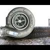
pm sent, interested in getting one of these badboys !

Who did you send the pm to?

if it was simark87 then he probably won't see it cos he hasn't been here since 19th July, 2006 - 08:23 AM.

If you want one, they're on ebay under turbotech.

Who did you send the pm to?

if it was simark87 then he probably won't see it cos he hasn't been here since 19th July, 2006 - 08:23 AM.

If you want one, they're on ebay under turbotech.

Dammit - lol - I just sent him a PM too!

I just sent him an email post number 52 says we can get them for $28 delivered, so I was just asking him about that not sure if he still uses that e-mail though.

I'll let you know if/when he gets to me if thats still the case for SkylinesAustralia members.

I just sent him an email post number 52 says we can get them for $28 delivered, so I was just asking him about that not sure if he still uses that e-mail though.

I'll let you know if/when he gets to me if thats still the case for SkylinesAustralia members.

[email protected] is his correct address.

They cost $37 delivered now.

hey all, since everyone seems to have drilled a hole in theirs, i went ahead and drilled mine as well. Not sure if its a little to big or not but it definately spools a whole lot faster.

Anyway what happens if the hole is too big?

And since the hole is letting boost get out to keep the wastegate shut, wouldnt that mean my turbo is working harder to create the same amount of pressure then if it wasnt drilled?

The hole is there to bleed the pressure between the actuator and the ball ONLY once the boost pressure drops to prevent the wastegate from staying open. due to the ball/hose/acutator creating a pressure vessel.

The downside to this is the hole will bleed boost like a traditional bleeder and as it tapers off at high RPM the boost will also drop off and make the controller less accurate.

This also means as some boost is bleeding off it would keep the actuator shut for a few 100ths of a second more. but would not make a difference in spool time.

My personal opinion is that the hole is not needed as it was in the original design and has since been dropped. I have used both and currently have the one without the hole and it holds a dead flat line for boost.

i was using mine with no hole too. it held boost great. had it on the dyno, showed a steady 10psi all the way till the end, then dropped slightly by less than 0.5psi. then i discovered i had a boost controller module connected to my unichip :D so i removed the turbotech, hooked the stock solenoid back up. set it to 10psi on the dyno, and it held the exact same boost pattern. needless to say, the turbotech was doing an excellent job. the only difference being, once i was back on the road, i discovered that the very slight lag on changes was now gone.

edit: also, one less defect in the engine bay :(

Edited by Munkyb0y
well it seems hes not selling them nemore coz theres no listing on ebay for them

i want to get myself another one coz i might have over drilled this one

I bought one 2 weeks ago.

Just did a quick search then and the item is still for sale?

http://cgi.ebay.com.au/ws/eBayISAPI.dll?Vi...s_promot_widget

well it seems hes not selling them nemore coz theres no listing on ebay for them

i want to get myself another one coz i might have over drilled this one

between 1 and 1.5 the hole needs to be if you drill.

are these the same as the jrd ones? on ebay???

i got one for my mate on his 180 and its bieng a pain in the ass. keeps spiking sometimes.

i noticed the spring inside is shit and gets bent and stuck. it this causing my boost spike problems?

and the difference between the two is?

we got a cooler on his lastnite and just plugged it all back up standard so its holding 9pound fine without that pain in the assssssss controler!

Edited by Angus Smart

Create an account or sign in to comment

You need to be a member in order to leave a comment

Create an account

Sign up for a new account in our community. It's easy!

Register a new account

Sign in

Already have an account? Sign in here.

Sign In Now


  • Similar Content

  • Latest Posts

    • Just had this happen to me too.  R32 GTR.   Also broke "just before going out onto the track" - someone up there is looking out for us... Very scary since I was about to do a narrow street course with zero run-off and curbs everywhere. Many people on here upgrading to billet uprights and R35 bearings?   Or buying new OEM knuckles?  I am not keen to replace with another s/h 30 year old fatigued part.
    • Top off with distilled water and see what happens. If you keep losing coolant then you know to start looking.
    • Nope.    Grab a varex and turn it down as you get close to home, win win? 
    • So, I've had my V36 for about a month now and have already copped an "excessive exhaust noise" notification from QLD TMR, reported by someone in my local area. It's a twin as per the original, and can have a bit of a throaty note to it when idling cold 😄 and if I do get up it a bit, it can be noisy, but it did pass a roadworthy inspection before sale, so.... ... but in the interest of being a good neighbour, I do want to quieten it down a bit. Is anyone here running a quiet aftermarket cat-back on their V36 or 370Z? And the big, bold question: does an aftermarket cat-back really make much of a performance difference on these cars?
    • The wiring diagram for the R33 RB25 is freely available, and is essentially the same same as most other RBs (just with differences as to which pin # does which job). To get the ECU to power up, you just need to provide power to the ECCS relay, and have the other power feeds that come in from the top left of the wiring diagram (wrt the ECU) that give perma power to the fuel pump relay, the ECU itself, etc etc, all connected. When you put power on all these it will just come to life. It's pretty clear from the diagram what needs to happen. Just follow the lines from the 12V + supply stuff in the top left over towards the ECU. I've even posted snips of such diagrams (not for vanilla 25, I think for Neo and 26) to various threads here in the last few months, talking about what it takes to get the fuel pump and FPCM up and going. Search these up and they will help get you started on doing the same with the vanilla 25 diagram. Hell, for all I know, I've done the same with that one in years past and have forgotten.
×
×
  • Create New...