Jump to content
SAU Community

Recommended Posts

i don't think they had obvious markings on them mate.

Well considering the three most common choices of cams in a RB25 heads are:

1. Stock cams

2. Poncams

3. HKS cams

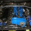
Then you should be able to tell (or post up some detailed pictures and I can tell you since I have had them all) which one of those three they are or if they look like something different.

Edited by PM-R33

He did mention he already has Poncams, installing an adjustable exhaust cam gear is silly, the Poncams have been already engineered for good mid response.

- Adjust your gain setting so the boost comes earlier

- post up your timing map, maybe your tuner was lazy and only tuned from columns 12+ to get you your kW figure and nothing else, you be amazed how many lazy tuners there are out there, that just subtract 5 degrees from the map from rows 15+ and then do a map trace and only tune on full throttle on the dyno

To be 100% sure they are aftermarket cams, pull camcovers off and measure the height of lobe and base circle diameter with vernier clamp.

Aftermarket cams should increase mid to high hp, torque. Can create a bow look to dynograph at lower rpms when cams have enough duration, lift. Also aggressive enough cams should create a lumpy idle (or stock / Tomei cams that had camgears adjusted). Tomei Poncams probably would have a smooth idle and look similar to stock cams, unless you adjust the camgears to make idle lump.

This dynograph shows what happens when intake, exhaust cams are adjusted on RB20DET (should be similar with RB25DET) -

http://www.uniqueautosports.com/Dyno/yx32gtstdyno.gif

Not to be rude but is blatantly clear that the ramp rate was changed for the both cam gear changed run to make it look better.... so the graph is pointless and misleading.

I agree with Ash. I would be looking at the boost controller settings. Most hiflows I have seen go straight to say 18psi, hold 18psi and then drop off at the end. Yours is 16psi at 3500rpm, 17psi at 4500rpm. It just gets over 17psi for a short time so I would hardly say its running 18psi.

Set it up to go straight to 18psi or even a bit higher and then leave it drop off to 16psi near redline. Especially in the lower revs it doesnt hurt to have a bit of extra boost to get going.

I dont think its an exhaust restriction because it still makes good top end power.

i wound the gain up from 19% to 30% (the max setting is 35%), and the start gain from 15psi to 15.5psi. it didnt make any difference as far as the seat of my pants is concerned. i still think its lacking power below 5000rpm.

will look at the other issues.

A whole 0.5psi :(

I know its a bit worrying but the tune should account for a bit more boost. if you are really worried try on a dyno. I would try 17psi so it flattens out to 18psi. will still be the same boost up top.

Edited by Harey
A whole 0.5psi :(

I know its a bit worrying but the tune should account for a bit more boost. if you are really worried try on a dyno. I would try 17psi so it flattens out to 18psi. will still be the same boost up top.

im not worried about running more boost. id happily run 25psi if it made more powah.

the set gain of 15/15.5 psi setting is when the ebc starts to regulate boost, according to the greddy manual. and they recommend setting this for 2-3 psi below desired pressure. yeah i can wind it up to maybe 17 or such, ill try it tomorrow.

would 1 psi at 3500-4500 really make much difference? cant hurt i guess!

Create an account or sign in to comment

You need to be a member in order to leave a comment

Create an account

Sign up for a new account in our community. It's easy!

Register a new account

Sign in

Already have an account? Sign in here.

Sign In Now


  • Similar Content

  • Latest Posts

    • For once a good news  It needed to be adjusted by that one nut and it is ok  At least something was easy But thank you very much for help. But a small issue is now(gearbox) that when the car is stationary you can hear "clinking" from gearbox so some of the bearing is 100% not that happy... It goes away once you push clutch so it is 100% gearbox. Just if you know...what that bearing could be? It sounding like "spun bearing" but it is louder.
    • Yeah, that's fine**. But the numbers you came up with are just wrong. Try it for yourself. Put in any voltage from the possible range and see what result you get. You get nonsense. ** When I say "fine", I mean, it's still shit. The very simple linear formula (slope & intercept) is shit for a sensor with a non-linear response. This is the curve, from your data above. Look at the CURVE! It's only really linear between about 30 and 90 °C. And if you used only that range to define a curve, it would be great. But you would go more and more wrong as you went to higher temps. And that is why the slope & intercept found when you use 50 and 150 as the end points is so bad halfway between those points. The real curve is a long way below the linear curve which just zips straight between the end points, like this one. You could probably use the same slope and a lower intercept, to move that straight line down, and spread the error out. But you would 5-10°C off in a lot of places. You'd need to say what temperature range you really wanted to be most right - say, 100 to 130, and plop the line closest to teh real curve in that region, which would make it quite wrong down at the lower temperatures. Let me just say that HPTuners are not being realistic in only allowing for a simple linear curve. 
    • I feel I should re-iterate. The above picture is the only option available in the software and the blurb from HP Tuners I quoted earlier is the only way to add data to it and that's the description they offer as to how to figure it out. The only fields available is the blank box after (Input/ ) and the box right before = Output. Those are the only numbers that can be entered.
    • No, your formula is arse backwards. Mine is totally different to yours, and is the one I said was bang on at 50 and 150. I'll put your data into Excel (actually it already is, chart it and fit a linear fit to it, aiming to make it evenly wrong across the whole span. But not now. Other things to do first.
    • God damnit. The only option I actually have in the software is the one that is screenshotted. I am glad that I at least got it right... for those two points. Would it actually change anything if I chose/used 80C and 120C as the two points instead? My brain wants to imagine the formula put into HPtuners would be the same equation, otherwise none of this makes sense to me, unless: 1) The formula you put into VCM Scanner/HPTuners is always linear 2) The two points/input pairs are only arbitrary to choose (as the documentation implies) IF the actual scaling of the sensor is linear. then 3) If the scaling is not linear, the two points you choose matter a great deal, because the formula will draw a line between those two points only.
×
×
  • Create New...