

Announcements
-
Similar Content
-
-
Latest Posts
-
By hoodedreeper · Posted
Initially I thought having a pair of Recaro seats would be a big bonus, it turns out these do get a little uncomfortable on long journeys (my fault, not the seat). I had a look through the GSM Performance website at reclining seats and booked an appointment to visit their show room. I got the Recaro Sportster CS for the R34 from here, was very happy with the service received so of course a re-visit was in order. Unfortunately the two Corbeau seats I had chosen aren't on display but they had 4 other options available. Two seats dug into my back, one dug into my legs and the other was perfect. I also found out that Recaro seats use a larger bolt pattern so some adaption was required. Luckily GSM offer some universal adaptors that should solve this problem. I searched the interwebs for price comparisons and Corbeau themselves were the cheapest at £300 cheaper (for the pair). I asked GSM if they could price match, unfortunately they couldn't. I later received an email saying Corbeau would honour them the same discount, but the purchase was already made. I did however order the brackets from GSM, both arrived on the same day. I started with the passenger side seat, knowing this was going to be a little trial and error. There are 3 mounting holes at the front and 2 at the rear on these JURAN Racing seat rails. With the adaptor brackets mounted, the allen cap bolts started to push into the seat, NOT GOOD! The rear mounting holes lined up but there were issues at the front. The holes were 1/2 hole out, so the brackets got a tickle with the drill to modify the holes. The supplied bolts weren't going to be long enough and a spacer was needed to stop the adaptor bars from bending. A local fasteners company supplied be with some nylon spacers and longer bolts (M8x30, although these will be replaced with 35mm long shortly) A before and after I pre-drilled the front bracket before making a start on the driver's seat to save some time. And in no time at all that was in the car too. The all black seats have transformed the interior and these are MUCH more comfortable. The only downside with the new Corbeau seats is I sit a little higher, but I'll happily accept that over discomfort. The Youtube video can be found here: https://www.youtube.com/watch?v=wPyttKPktXA -
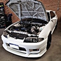
 All 3 I guess. The car came with the JASI Aero 4 door Type R Full Kit unpainted so this was one thing at the top of my list to complete then I noticed there were body panels parts for this kit so i picked them up along with some black mesh to fill in the front bumper and front side air vents. car is at a paint and body shop atm completing this work. Next I will be addressing the internal bells and whistles, great summer project I can do with the kids. full interior removal - ,boys car sound deadening - pads and spray ,boys stereo, sound, lighting - Big 3, GTT or bigger alternator ,kids head lining - dye black add star lighting mod ,daughter. That's it for the next 5-6 months. I have some motor maintenance work i have to plan out. oil filter relocation, gaskets, mounts. beyond that, mind is starting to turn over if i can use a DET intake plenum, block off turbo ports & pipe in a air intake.
 -
roller coaster of a ride. Alarm system was removed & main harness was repaired where possible. still no fix just random successful starts. moved on to the replacing the ignition switch and relay. well all this troubleshooting & repair has been going on, the car is at a paint and body shop being pushed around. Ive been going down there on odd days after work to get it sorted.
-
 5th November if you want to come out for a spin wakfield
 -
 PROBLEM WAS BROKEN COOLANT SENSOR!!! Replaced with a new one and its running mint.
-


Recommended Posts
Create an account or sign in to comment
You need to be a member in order to leave a comment
Create an account
Sign up for a new account in our community. It's easy!
Register a new accountSign in
Already have an account? Sign in here.
Sign In Now