
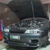
93 R32 Gtr Street Monster!
Announcements
-
Similar Content
-
-
Latest Posts
-

-

By Dose Pipe Sutututu · Posted
Should be more than fine, especially the overall fuel pressure would never exceed 3.5bar (assuming that thing never gets more than 0.5bar of boost in stock form). According to the chart, it's 11amps. -
.thumb.jpg.1b7f9b555236b5ea56c3fed20c733de8.jpg)
By iain_ST44GA · Posted
I definitely know the first rule here, look first, ask second. I've seen many people get roasted 😂 I found a few diagrams for the RB, but I'm yet to come across one for the VQ. From what I have read, the pump gets the +12v along with the FPCM, and it's the negative wire that gets passed through the resistor to regulate the voltage. So I assume I can just ground the negative wire at the pump to eliminate the FPCM control. But I really wanted to see the VQ circuit diagram first to make sure I understood it correctly. Once the new pump is in I'll do some testing to see how it behaves, and in the meantime, I'll keep looking for a wiring diagram. Thanks for your help mate, your time is greatly appreciated. -
 Maybe? I have the Supercheap ToolPro low thingo. It has a somewhat smaller diameter lifting "bowl" than you would expect on a workshop grade trolley jack, and a split rubber pad to suit that diameter. It clears the "N1" style skirts I have. Probably wouldn't if the jack's bowl and a suitably larger rubber block were in use. Having said that though.....you only need the rubber block to exist on the inner side of the pinchweld, so could carve away any rubber that fouled the skirt, leaving some there for "insurance" </simples>
 -
 I used to do that (sills with rubber jack block).. ... then I got side skirts, and there's no way for the jack to actually work there, the jack pad itself on the jack is too big. Is the answer to use a... smaller (?) jack? Hmmm.
-


.thumb.jpg.1b7f9b555236b5ea56c3fed20c733de8.jpg)

Recommended Posts
Create an account or sign in to comment
You need to be a member in order to leave a comment
Create an account
Sign up for a new account in our community. It's easy!
Register a new accountSign in
Already have an account? Sign in here.
Sign In Now