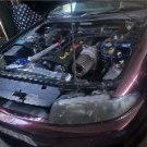
Texi Wrap Up 22/03/2015
Announcements
-
Similar Content
-
Latest Posts
-
Ok guys thank you very much. GCG highflow it is then 🙂
-
forgot to mention that when it does this it does not kill the engine, but I have not kept the pedal down long enough to let it, as I see no reason to beat up on it as its got to be something simple, small and dumb causing this. And as soon as I let off pedal, the engine returns to its normal super smooth operation and rpms re-stabilize quickly, once below 4k.
-
neither stumble or cut really seem to be an appropriate term....hard to explain its like a rev limiter but at 4k, but it violently shakes engine and entire vehicle as the rpms will not rise over 4k, even with slow acceleration. as soon as it hits 4k, it sounds like entire spark is lost entirely. plugs were 1.1 which I used as such, but later put in new plugs gapped down to .8 changed back after issue arose when I replaced the coils, still does it with either plug gap...damn and it was all running so good.
-
By TurboTapin · Posted
Oh how times have changed! I actually lean it out relative to my water/methanol injector duty cycle. The methanol adds a lot of fueling and you can then lean it out even more due to reduced knock. -
By Dose Pipe Sutututu · Posted
Yeah my thoughts are the same, a well thought out WMI setup, would be slightly ahead of just straight E85 and you're also chemically intercooling the charged air, dropping it even further. This is why you need to add so much more fuel as soon as you spray. I remember someone taking me through their set up before (Dennis, has a R33, lives around Cabramatta - no idea if he's still around on this forum). He would target AFR 10:1 on 98, then as WMI ramped on, AFR would lean back up to 11:1. Amazingly, he did this all through his PowerFC, a relay to cut power to his EBC solenoid if there was not enough line pressure on his WMI kit. And of course, if there wasn't any boost made above gate pressure, you wouldn't be accessing the load cells with heaps of timing for WMI. One downside to that rudimentary setup, once the WMI came on, the EBC would unleash the dragon, and of course all the timing. Tyres would fry lol.
-


Recommended Posts
Create an account or sign in to comment
You need to be a member in order to leave a comment
Create an account
Sign up for a new account in our community. It's easy!
Register a new accountSign in
Already have an account? Sign in here.
Sign In Now