Jump to content
SAU Community

Recommended Posts

2 hours ago, TimmyMA70 said:

I have access to a more industrial type of bead blasting cabinet. The media in it is glass base. It's excellent as it doesn't blast too deep and is good for finer objects.


Nice. Its done a great job!

2 hours ago, TimmyMA70 said:

I really like the GTIR bonnets, they are unique and are a 90's icon. Although unfortunately I believe they belong on one car, a GTIR. 

1

You're not one of these crazys who thinks GTR badges are for GTRs only are you?!?


  • Like 2
10 hours ago, PranK said:

Nice. Its done a great job!

You're not one of these crazys who thinks GTR badges are for GTRs only are you?!?


Ahh yes and no. A GTR badge is a much more subtle change VS a very unique bonnet. I also think that the gtir bonnet is the most overdone mod to an Aus N14. Nearly any N14 with P plates on it has the IR bonnet. Plus I'm anal as hell, and those vents are only going to let water drip down onto the rocker cover and plug leads (GTIR has a cover which goes over the top of the leads) :5_smiley:

You are dead on about the Gtir bonnet. :laugh:

Had a Gtir and even with the cover it was basically useless.

When it rained, it constantly had water running into the lead recess and caused issues!

Would put out cylinder 1 plug and it would be covered in old rusty water.

WD40 x 10000 

  • Like 1
19 hours ago, intercpt said:

You are dead on about the Gtir bonnet. 

Had a Gtir and even with the cover it was basically useless.

When it rained, it constantly had water running into the lead recess and caused issues!

Would put out cylinder 1 plug and it would be covered in old rusty water.

WD40 x 10000 


Hahaha, my suspicions verified. I don't think I could handle it.

You get it though. :P

  • Like 1

Alright guys:

Calipers are officially rebuilt. Extremely happy with them!

20170624_102459_zpsq5lvxnb8.jpg

So previously rear brakes upgrade on an N14 was limited to GTIR rear calipers OR GTIR calipers with A32 Maxima rear caliper carriers (brackets) to space the caliper out to fit a 278mm rear A32 Maxima rotor in there. The issue with this is GTIR use a 33mm hat height rotor and A32 use a 45mm hat height. So you would have to put a 22mm spacer in between the hub and the rotor.

I have done some searching and discovered that the 2002 - 2005 Ford Focus ST170 rear rotors are 280mm, 33mm hat height. The only things required to make them fit is change the PCD from 4x10⁸ to 4x100 and machine out the centerbore from 64mm to 68mm. Basic machining. The rotor thickness is also 10.3mm VS 9mm Worst case scenario the rotor may need a skim to get them to fit.

Machining should happen this week, hopefully do a fit up next weekend.

20170624_103130_zps33y5vdoa.jpg

20170624_103120_zpsgbdsmytg.jpg

20170624_103326_zps3x9y1f8l.jpg

20170624_103304_zps6qm6myou.jpg

  • 11 months later...

So now I've converted all my photos over to Imgur, I can actually do some decent updates.

I've had my driveshafts overhauled, completely OEM, new grease and new boots, zero wear in the joints themselves!

W6j7wYZh.jpg

I bought myself a P11 SR20VE too, from a Pulsar Group of Australia member. It'll get a freshen up before it goes in.

pZ6Q0pYh.jpg

yyqr3zph.jpg

My N16 hubs, pressed apart.

TIvrdiVh.jpg

Redrilled to 4x100

1OkGHJGh.jpg

Gave the rear of the hubs a hit with some VHT Black high temp paint.

3myTJLnh.jpg

Front brakes done:
A32 Maxima Calipers, A32 Maxima 280mm rotors redrilled to 4x100, N16 Hubs redrilled to 4x100

6p0vFyWh.jpg

I went to bolt the rear brakes up and the caliper ended up needing spacing to align the caliper bracket to the center of the rotor:

SRanH1qh.jpg

06g57BLh.jpg

sJSzwaXh.jpg

Brakes on, time for a wheel test fit:

8fWAfbTh.jpg

wtCbfsgh.jpg

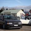
The red rocket is off the hoist! ... Well just for a few happy snaps anyway. I'm still waiting on some braided brake lines to finish off the brakes.

Please excuse the inch of dust on the body and the lack of shine to the paint and all the other body defects it has at the moment!

mxHzX9Rh.jpg

mxHzX9Rh.jpg

y2qSR3Bh.jpg

UwVSgHsh.jpg

OTPEsAbh.jpg

I bought a set of Kumho V720 tyres. I used to run the KU36's on my old N15, these are a revised version of those. I'm keen to see how they perform.

TeoUKQZh.jpg

So, wheel alignment time:

This was all done by me with the help of a very talented mate.

QxK5sSph.jpg

lIId9Mwh.jpg

I6V6YFHh.jpg

As you can see, castor isn't ideal, so time for some castor adjusting bushes.


This is a 32V VZR Gearbox I picked up to do my manual conversion

Pretty grubby hey...

dsLI2Eyh.jpg

HTr5sAqh.jpg

vEILS0Yh.jpg


Alot cleaner now :)

BfwToHih.jpg

UpxK5bnh.jpg

J1XOkryh.jpg

30vWkpnh.jpg


Auto is out!! Finally!!

jNCtDK7h.jpg

ZHLL3dxh.jpg

Freshly machined PAR 4.1kg flywheel fitted up and new Xtreme HD Organic Clutch

obWpt8ph.jpg

I did the hydro conversion while I was going.

Fitted a turbine oil impegnated sintered bronze bush to the GTiR clutch pedal, for a buttery smooth feel.

Jvd7fUWh.jpg

RGNpv6jh.jpg

  • Like 1

Bought some Protech 4-1's for the VE build, these are used from another member, stepped 4-1's to give some decent torque down low, although 4-1's to keep the VE screaming up top. That is a 3" V band...

UuNDyZ4h.jpg

ASFfelEh.jpg

Stripped the VE down ready for some love

VwKCE8Wh.jpg

weXJd3ch.jpg

MlyxggUh.jpg

Then I went back to the VE head, tried my hand at a bit of light porting, a mate of mine is giving me a hand, this porting is just the cleanup stage:

Intake Before:

OgGYTShh.jpg

After:

98kanYXh.jpg

VufIjDkh.jpg


Exhaust Before:

Z5Zth0bh.jpg

After:

QGrWVhrh.jpg

Bought myself a burette to make sure I wasn't getting too carried away on one port more than the other.

8PSq6CDh.jpg

gPW5HWWh.jpg

The porting work hasn't finished just yet. Still doing bits and pieces on it from time to time. Next up - Track Prep ;)

Edited by TimmyMA70
  • Like 1

Then the carpet was stripped out, to fit the brackets, rails and seat out.

G42BsOlh.jpg

Then...

Dry ice time, my wife gave me a hand removing all the sound deadening. She thought it was great fun.

iQvErHch.jpg

FWDl0MSh.jpg

O2v9nZjh.jpg

CBDUBH7h.jpg

In total 30kg's of sound deadening was removed, including the firewall mat.

A coat of paint now, to protect that exposed primer

gOIz7dsh.jpg

8VkPviBh.jpg

Also, reinstalled 3kg's worth of Dynaliner to try and help with heat coming through the floor

pMLLTrah.jpg

bIbmkBrh.jpg

Harness bar test fit while the seats are out

POE0S5gh.jpg

60PrVpAh.jpg

IcRXDG2h.jpg

Hey guys, another update.

I finished painting the primed areas in the boot area where the sound deadening was removed, also finished clipping the battery cable to the floor pan, keep everything as neat as possible.

kN4EERYh.jpg

yIGOJNlh.jpg

I finished cc'ing my intake ports yesterday:

#1 - 169.1cc

#2 - 169.1cc

#3 - 169.2cc

#4 169.2 cc

Now they're really close, I can finish the ports off :D

C4af10Gh.jpg

Alright this is the last post and this thread is completely updated :)

So after going over everything before this fast approaching track day, I noticed a little green drip from the water pump tell tale hole. So decided to err on the side of caution and throw a new pump at it before the track day. Checked all the coolant hoses, disconnected all the coolant lines from the intake manifold and looped them, also disconnected and looped the lines from the throttle body.

BIWk5Wvl.jpg

I had to release all 4 engine mounts to be able to have enough clearance between the chassis rail and the water pump, which meant removing the airbox. Since I made it I have always wanted to paint it satin black, so prepped it up and gave it a coat of paint.

vF9h1jEl.jpg

Then I finished my seat brackets to mount the pair of Sparco Pro 2000's which I am running.

j9udUnZl.jpg

pMrWeMDl.jpg

PIhb0Bal.jpg

That's all from me for now :)

Thanks for reading.

  • Like 3

Create an account or sign in to comment

You need to be a member in order to leave a comment

Create an account

Sign up for a new account in our community. It's easy!

Register a new account

Sign in

Already have an account? Sign in here.

Sign In Now


  • Similar Content

  • Latest Posts

    • For once a good news  It needed to be adjusted by that one nut and it is ok  At least something was easy But thank you very much for help. But a small issue is now(gearbox) that when the car is stationary you can hear "clinking" from gearbox so some of the bearing is 100% not that happy... It goes away once you push clutch so it is 100% gearbox. Just if you know...what that bearing could be? It sounding like "spun bearing" but it is louder.
    • Yeah, that's fine**. But the numbers you came up with are just wrong. Try it for yourself. Put in any voltage from the possible range and see what result you get. You get nonsense. ** When I say "fine", I mean, it's still shit. The very simple linear formula (slope & intercept) is shit for a sensor with a non-linear response. This is the curve, from your data above. Look at the CURVE! It's only really linear between about 30 and 90 °C. And if you used only that range to define a curve, it would be great. But you would go more and more wrong as you went to higher temps. And that is why the slope & intercept found when you use 50 and 150 as the end points is so bad halfway between those points. The real curve is a long way below the linear curve which just zips straight between the end points, like this one. You could probably use the same slope and a lower intercept, to move that straight line down, and spread the error out. But you would 5-10°C off in a lot of places. You'd need to say what temperature range you really wanted to be most right - say, 100 to 130, and plop the line closest to teh real curve in that region, which would make it quite wrong down at the lower temperatures. Let me just say that HPTuners are not being realistic in only allowing for a simple linear curve. 
    • I feel I should re-iterate. The above picture is the only option available in the software and the blurb from HP Tuners I quoted earlier is the only way to add data to it and that's the description they offer as to how to figure it out. The only fields available is the blank box after (Input/ ) and the box right before = Output. Those are the only numbers that can be entered.
    • No, your formula is arse backwards. Mine is totally different to yours, and is the one I said was bang on at 50 and 150. I'll put your data into Excel (actually it already is, chart it and fit a linear fit to it, aiming to make it evenly wrong across the whole span. But not now. Other things to do first.
    • God damnit. The only option I actually have in the software is the one that is screenshotted. I am glad that I at least got it right... for those two points. Would it actually change anything if I chose/used 80C and 120C as the two points instead? My brain wants to imagine the formula put into HPtuners would be the same equation, otherwise none of this makes sense to me, unless: 1) The formula you put into VCM Scanner/HPTuners is always linear 2) The two points/input pairs are only arbitrary to choose (as the documentation implies) IF the actual scaling of the sensor is linear. then 3) If the scaling is not linear, the two points you choose matter a great deal, because the formula will draw a line between those two points only.
×
×
  • Create New...