Project 24
Announcements
-
Similar Content
-
Latest Posts
-
Even more fun, leave all the ADAS stuff plugged in, but in different locations, hopefully avoid any codes! And honestly, all these new cars with their weird electronics. Pull all the electronics out Duncan, and just shove an aftermarket ECU and if needed a trans controller in, along with a PDM. Make it run basic but race car styled!
-
To follow up a question from earlier too since I had the front bar off again (fking!) This is what is between the bumper and the drivers side wheel And this is the navigator side, only one thing but its a biggy! So basically....no putting coolers in the wheel arches without a lot of moving other stuff. Assuming I move to properly race prepping this car I'll take that job on and see how the computers respond to removing a whole bunch of ADAS modules
-
So I prepped the car for another track day on Wednesday (will be interesting to see coolant temps post flushing out and the larger reservoir, with a forecast of 3-14 being 20o cooler than last time I took it out). Couple of things to mention; since I am just driving the car and not taking a support vehicle, I took the rear seats out and just loaded the back up Team Trackday style. Look at all that space! To cover off removing the rear seat....it is weird (note the hybrid is probably different because it wouldn't have folding rear seats) Basically, you remove the lower seat base, very similar to a r series but it is a clip that pulls forward to release the base rather than it being bolted down. Easy Then, you need to remove the side section of the rear seat on each side. There is a 14mm head nut at the bottom of the side piece, the it slides upwards off a hook at the top to release; you also need to unhook the seatbelt from the loop at the top. Then the centre piece is weird. You need to release/fold the seats forward with the tab in the boot on each side From there, there are 2,x12mm headed bolts holding the rear of each seat to the folding bracket, under the trim between the rear seat and the boot (4x christmas tree clips there, they suck). The seat is out but you can see where the bolts attach to the bracket
-
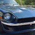
As discussed in the previous post, the bushes in the 110 needed replacing. I took this opportunity to replace the castor bushes, the front lower control arm, lower the car and get the alignment dialled in with new tyres. I took it down to Alignment Motorsports on the GC to get this work done and also get more out of the Shockworks as I felt like I wasn't getting the full use out of them. To cut a very long story short, it ended up being the case the passenger side castor arm wouldn't accept the brand new bush as the sleeve had worn badly enough to the point you could push the new bush in by hand and completely through. Trying a pair of TRD bushes didn't fix the issue either (I had originally gone with Hardrace bushes). We needed to urgently source another castor arm, and thankfully this was sourced and the guys at the shop worked on my car until 7pm on a Saturday to get everything done. The car rides a lot nicer now with the suspension dialled in properly. Lowered the car a little as well to suit the lower profile front tyres, and just bring the car down generally. Eternally thankful for the guys down at the shop to get the car sorted, we both pulled big favours from our contacts to get it done on the Saturday. Also plugged in the new Stedi foglights into the S15, and even from a quick test in the garage I'm keen to see how they look out on the road. I had some concerns about the length of the LED body and whether it'd fit in the foglight housing but it's fine. I've got a small window coming up next month where I'll likely get a little paint work done on the 110 to remove the rear wing, add a boot wing and roof wing, get the side skirt fixed up and colour match the little panel on the tail lights so that I can install some badges that I've kept in storage. I'm also tempted to put in a new pair of headlights on the 110. Until then, here's some more pictures from Easter this year.
-
By joshuaho96 · Posted
I would put a fuel pressure gauge between the filter and the fuel rail, see if it's maintaining good fuel pressure at idle going up to the point when it stalls. Do you see any strange behavior in commanded fuel leading up to the point when it stalls? You might have to start going through the service manual and doing a long list of sensor tests if it's not the fuel system for whatever reason.
-


1.thumb.png.36afd656b26d55f5d425fc76e21561f2.png)


Recommended Posts
Create an account or sign in to comment
You need to be a member in order to leave a comment
Create an account
Sign up for a new account in our community. It's easy!
Register a new accountSign in
Already have an account? Sign in here.
Sign In Now