Jump to content
SAU Community

Recommended Posts

Why not get the stuff ceramic coated? It is so so so much better than that wrap stuff...

i was under impression that when you wrap it, all it does is keep the heat in, so it will eventually crack the steel or what ever it is you wrap. Also, if you try unwrapping it, it would have basically stuck it self to the metal, so it peels away the steel making it really fragile and weak. I just had my stuff coated, 600 for manifold, dump and exhaust housing. It is so much better.

You have gone to all the effort of doing everything else right, i think you should ceramic coat it while engine is still out :P Keeps so much more heat out of the engine bay also!

Hey mate you should look into getting a stainless steel turbo drain made up as the hose you are using will handle the temp but it will deform and knick when it heats up causing the hose to block the oil flow slightly.

I can see that oil drain being an issue from the first dyno session. Save yourself some time now and have a hard line made. Like Fineline, all my lines are going to be steel. I'll have some pics in the next week

bit late to mention it now, but since you have a forward facing plenum i would have used rb26 rocker covers which look nicer and also have the pcv hosing up the back.

That stock black hose will be replaced with lines from the Greddy oil catch can. So wont look as bad. Plus it is a 25 not a 26.I did consider the 26 covers though but decided against it.

I got that oil line from Earls. Was told it would be up to the job easy. Plus im heat wrapping the manifold so the heat will not be as intense.

Please yourself dude. they told us all the same things and we did all the same things and more to prevent issues with the braided lines but it still shit itself.

I hope yours doesnt but from personal experience you are running a risk. It cost me a turbo. :D

i would aslo guess at saying the water feed you have installed will foul on the strut tower. innner guard, whatever you want to call it.

ring ETM, he can send you a stainless oil return off the shelf to suit your aplication.

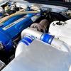
heres what i did with anna's engine...

Dave, Anna; does the AC still work in that car? Im suprised how much you've been able to bend the firewall AC fittings.

Just in the process of replacing the braid down through the manifold with hard lines.

Do you think the expansion and growth of the manifold and turbo (when hot) requires any special consideration when running hard steel lines? Ive been wondering if loops should be made to assist the tube fittings in taking load.

i would aslo guess at saying the water feed you have installed will foul on the strut tower. innner guard, whatever you want to call it.

ring ETM, he can send you a stainless oil return off the shelf to suit your aplication.

+1

That water feed looks way to far out :blink: Might still work... be interesting to see the final result once its in. My guess is it will be tight if it does fit...

Is that an xforce manifold?? I have heard that they crack fairly easily from people that have run them.... might pay to HPC it now while its still out of the car .... Wrapping wont help unfortunately... I have seen one die after 2 months. He HPC'd (black same as mine) the next one (ebay jobby) and it lasted over 2 years on a 400+rwkw GTR

otherwise... looking good... how long till its going in??

Dave, Anna; does the AC still work in that car? Im suprised how much you've been able to bend the firewall AC fittings.

Yup sure does.... just a little gentle persuasion :(.... I refused to lose the air con seeing as my car is black. I bent them the first time round (majority of it) as my old tuner didnt want to be held responsible if it stopped working !! lol!!

Dave bent them a little more once the new engine was in....

Only bent to keep them away from the manifold a bit more... its all a bit of a tight fit otherwise...

P.s it didn't work at first as we forgot to plug the compressor clutch back in!! whoops!! :blink:

just wondering if anyone can help me with a problem with my rs4 s stagea?

it's surging while driving.

i already done coil packs . changed to splitfire.

using boash double platniums with gap 1.0mm. splitfire coils should jump that gap easy. no mod's only panel filter

i'm thinking air flow meter?

it seems to drive ok when cold but then if it hit a bump it starts to surg? and once it gets warm

but saying all that it comes and go's.

i also read that the soldering joints can break inside air flow meter. which would explan why it comes and go's

thanks ant

Only bent to keep them away from the manifold a bit more... its all a bit of a tight fit otherwise...

Tight fit, tell me about it! I'm just jealous i didn't have the balls to bend them like that :blink: Iv had to angle my dump pipe towards the motor to clear them, giving me about 10mm.

Cheers!

Tight fit, tell me about it! I'm just jealous i didn't have the balls to bend them like that :blink: Iv had to angle my dump pipe towards the motor to clear them, giving me about 10mm.

Cheers!

Yeah just bend em, DONT try and bend em back though!! They will snap... bit like copper hot water pipes etc... it hardens as soon as you move it..

Lol re the balls... I didn't really think of the ramifications if it farked up... just all guns blazing and yeah.. happy ending! thank god!!

just wondering if anyone can help me with a problem with my rs4 s stagea?

it's surging while driving.

i already done coil packs . changed to splitfire.

using boash double platniums with gap 1.0mm. splitfire coils should jump that gap easy. no mod's only panel filter

i'm thinking air flow meter?

it seems to drive ok when cold but then if it hit a bump it starts to surg? and once it gets warm

but saying all that it comes and go's.

i also read that the soldering joints can break inside air flow meter. which would explan why it comes and go's

thanks ant

LMAO thats funny as..

Back on topic it sounds like its going well, I can't wait to see power figures.

Create an account or sign in to comment

You need to be a member in order to leave a comment

Create an account

Sign up for a new account in our community. It's easy!

Register a new account

Sign in

Already have an account? Sign in here.

Sign In Now


  • Similar Content

  • Latest Posts

    • Yeah, that's fine**. But the numbers you came up with are just wrong. Try it for yourself. Put in any voltage from the possible range and see what result you get. You get nonsense. ** When I say "fine", I mean, it's still shit. The very simple linear formula (slope & intercept) is shit for a sensor with a non-linear response. This is the curve, from your data above. Look at the CURVE! It's only really linear between about 30 and 90 °C. And if you used only that range to define a curve, it would be great. But you would go more and more wrong as you went to higher temps. And that is why the slope & intercept found when you use 50 and 150 as the end points is so bad halfway between those points. The real curve is a long way below the linear curve which just zips straight between the end points, like this one. You could probably use the same slope and a lower intercept, to move that straight line down, and spread the error out. But you would 5-10°C off in a lot of places. You'd need to say what temperature range you really wanted to be most right - say, 100 to 130, and plop the line closest to teh real curve in that region, which would make it quite wrong down at the lower temperatures. Let me just say that HPTuners are not being realistic in only allowing for a simple linear curve. 
    • I feel I should re-iterate. The above picture is the only option available in the software and the blurb from HP Tuners I quoted earlier is the only way to add data to it and that's the description they offer as to how to figure it out. The only fields available is the blank box after (Input/ ) and the box right before = Output. Those are the only numbers that can be entered.
    • No, your formula is arse backwards. Mine is totally different to yours, and is the one I said was bang on at 50 and 150. I'll put your data into Excel (actually it already is, chart it and fit a linear fit to it, aiming to make it evenly wrong across the whole span. But not now. Other things to do first.
    • God damnit. The only option I actually have in the software is the one that is screenshotted. I am glad that I at least got it right... for those two points. Would it actually change anything if I chose/used 80C and 120C as the two points instead? My brain wants to imagine the formula put into HPtuners would be the same equation, otherwise none of this makes sense to me, unless: 1) The formula you put into VCM Scanner/HPTuners is always linear 2) The two points/input pairs are only arbitrary to choose (as the documentation implies) IF the actual scaling of the sensor is linear. then 3) If the scaling is not linear, the two points you choose matter a great deal, because the formula will draw a line between those two points only.
    • Nah, that is hella wrong. If I do a simple linear between 150°C (0.407v) and 50°C (2.98v) I get the formula Temperature = -38.8651*voltage + 165.8181 It is perfectly correct at 50 and 150, but it is as much as 20° out in the region of 110°C, because the actual data is significantly non-linear there. It is no more than 4° out down at the lowest temperatures, but is is seriously shit almost everywhere. I cannot believe that the instruction is to do a 2 point linear fit. I would say the method I used previously would have to be better.
×
×
  • Create New...