Jump to content
SAU Community

Recommended Posts

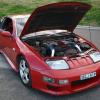
Item: Purvis Eureka Kit car

Location: Sydney

Item Condition: Good

Reason for Selling: If it sells it sells if not i keep it. Don't really have time to fix at the moment.

Price and Payment Conditions: $5,500 WILL NOT DROP ANY LOWER, Not taking parts off to lower price, you take the car you take it all.

Extra Info:

Motor is apart, its a Vw 1500cc.

1.5" Bugpack Megadual Exhausts

Chrome Air filter

Lumpy Camshaft

Honed cylinders

EMPI Oil Cooler

Lexcen headlamp Covers - Bubbles in right side of Tint, will fix. Tint 35%.

Lexcen Smoked Side Windows - Custom made $400 new

Lambo Air Intake scoops

70's style side mirrors

Hydraulic Rams for Roof lift - New seals $100

Hydraulic pump for roof lift

Type R Wheel

Quick Release Boss Kit

Autotechnica Pedal Pads

Chrome Shifter

Monza Gearboot

Full Set of VDO Gauges

14" Bathurst Globe Rims (F:205/70, R:235/60)

VW 1500 4spd Transaxle - Has been flushed out

Valeo Heavy Duty Clutch + stock clutch

Valeo Pressure Plate + Stock P/plate

Short Shifter

Bilstein Gas Shocks

Rebuilt Front calipers

Brembo Front disk Rotors

Rebuilt Rear Drums

New Master Cylinder

Car Weigh's 780kg, with a nice paintjob and a 12A rotor it would go pretty good. New Floorpan has been welded in & painted.

All interior trim is there, wiring works, have all previous rego & engineer certs.

Car needs:

Motor: Either this one rebuilt - $1-2k, $200 ebay one or even your own motor you want to stick in.

Seats: Will Need to be from a smaller car - $?

and Rego: Car complies with all ADR's

Paint

For $3-4k you have a car worth $15k

Pictures:

Yep

Contact Details:

Pm me

In about two months time if it does not sell i will be putting in a Forged Vdub motor(ready for turbo), as of then price will be $8,500

post-29561-1236514395_thumb.jpg

post-29561-1236514522_thumb.jpg

Link to comment
https://www.sau.com.au/forums/topic/260205-fs-purvis-eureka-f4/
Share on other sites

  • 2 months later...

Bump, motor has been rebuilt to standard spec(by my old man) but has not been put into the car or started. Price is $6,000, will also trade for a more expensive car + cash(upto $5000) your way if necessary. Prefer R33 Non turbo.

  • 2 weeks later...
  • 2 weeks later...
  • 11 months later...
  • 5 years later...
  • 1 month later...
Guest
This topic is now closed to further replies.


  • Latest Posts

    • For once a good news  It needed to be adjusted by that one nut and it is ok  At least something was easy But thank you very much for help. But a small issue is now(gearbox) that when the car is stationary you can hear "clinking" from gearbox so some of the bearing is 100% not that happy... It goes away once you push clutch so it is 100% gearbox. Just if you know...what that bearing could be? It sounding like "spun bearing" but it is louder.
    • Yeah, that's fine**. But the numbers you came up with are just wrong. Try it for yourself. Put in any voltage from the possible range and see what result you get. You get nonsense. ** When I say "fine", I mean, it's still shit. The very simple linear formula (slope & intercept) is shit for a sensor with a non-linear response. This is the curve, from your data above. Look at the CURVE! It's only really linear between about 30 and 90 °C. And if you used only that range to define a curve, it would be great. But you would go more and more wrong as you went to higher temps. And that is why the slope & intercept found when you use 50 and 150 as the end points is so bad halfway between those points. The real curve is a long way below the linear curve which just zips straight between the end points, like this one. You could probably use the same slope and a lower intercept, to move that straight line down, and spread the error out. But you would 5-10°C off in a lot of places. You'd need to say what temperature range you really wanted to be most right - say, 100 to 130, and plop the line closest to teh real curve in that region, which would make it quite wrong down at the lower temperatures. Let me just say that HPTuners are not being realistic in only allowing for a simple linear curve. 
    • I feel I should re-iterate. The above picture is the only option available in the software and the blurb from HP Tuners I quoted earlier is the only way to add data to it and that's the description they offer as to how to figure it out. The only fields available is the blank box after (Input/ ) and the box right before = Output. Those are the only numbers that can be entered.
    • No, your formula is arse backwards. Mine is totally different to yours, and is the one I said was bang on at 50 and 150. I'll put your data into Excel (actually it already is, chart it and fit a linear fit to it, aiming to make it evenly wrong across the whole span. But not now. Other things to do first.
    • God damnit. The only option I actually have in the software is the one that is screenshotted. I am glad that I at least got it right... for those two points. Would it actually change anything if I chose/used 80C and 120C as the two points instead? My brain wants to imagine the formula put into HPtuners would be the same equation, otherwise none of this makes sense to me, unless: 1) The formula you put into VCM Scanner/HPTuners is always linear 2) The two points/input pairs are only arbitrary to choose (as the documentation implies) IF the actual scaling of the sensor is linear. then 3) If the scaling is not linear, the two points you choose matter a great deal, because the formula will draw a line between those two points only.
×
×
  • Create New...