Jump to content
SAU Community

Recommended Posts

  • 2 weeks later...

More progress. Initially was going to do the bay and interior grey, but ended up getting some paint mixed up to the same colour as the outside so will be painting the inside to match the outside now.

IMG_3148.jpg

IMG_3149.jpg

IMG_3150.jpg

IMG_3151.jpg

  • Like 1
  • 2 weeks later...

Designed some solid engine mounts which will also sit the engine 175mm further back. Bolts up to all the standard mounts. Yet to FEA them to see if they're strong enough but I'm sure they will be...

Will 3D print them for test fitting before making any final adjustments to the design. Might also lower then engine 50mm if possible. Will have to wait on the new dry sump to know how low I can go.

DR30-engine-mounts.PNG

Edited by clubracer

Standard firewall will remain in place. Because the 30 originally had the 6, they mounted the 4 at the same forward point meaning a heap of room between the engine and firewall. Even the hole in the tunnel for the shifter is elongated and moving the box back 175mm wont even need a new hole cut.

  • 3 weeks later...

I've been moving house, then moving house, then moving house.... yes three times in the space of two months.... but finally, it's over. My funds have been depleted but I'll start saving again to get this project finished! I did manage to buy a few goodies before the funds managed to make their way into a range of greedy and sneeky real estate agents and tradesmans' pockets though...

The Borg Warner EFR is the best off-the-shelf option for improved production, although not strictly heading down that route now, it's good for over 400hp and is T2 based so will have unreal response. So far I dont know anyone who has an EFR on an FJ20. With the compression at 9.5 it should make for a really sweet little engine. And with the standard gearbox behind hopefully it wont be too mean with a much more linear power delivery.

I also managed to pickup this GTS-R spec (I think!) diff cover which is finned, has extra capacity and come from the factory with blanked holes for cooler lines. This will get fitted once I have the diff freshened up.

borg-warner.jpg

borg-warner-manifold.jpg

diff-cover.jpg

  • Like 1
  • 3 months later...

So there's been a pretty big change of plans... In time will be selling the suspension, steering and brakes. All of it brand new or rebuilt. About 8K worth.

We are going double wishbone front and rear with our own uprights and brake callipers, so the whole braking, suspension, wheels/tyres and steering setup will have to go. Everything is custom made so that it bolts up to factory. Is 8K just in parts, and all the man hours on design work...

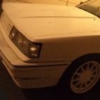
skyline-smaller.jpg

  • Like 1
  • 2 weeks later...

Yeah I know people will either love it or hate it, but at the end of the day I need to promote the business, and I want to do it with something that is a bit different that will stand out from the crowd. It'll be quite classic looking. No super modern wheels and crazy crazy aero, but clean lines and will actually do the shape justice.

Under the body is where it will all be happening though. Have completely bespoke and geometry optimised suspension with a double wishbone setup front and rear. Am designing some pretty trick rear uprights that keep the lower wishbone inline with the drive shaft so that the nice big aero tunnels don't get disturbed. We will also be mounting the callipers at the bottom of the uprights, further improving the C of G. Although there are lighter wheels around our own design will mean no restrictions. Mourning the front wheel cover will then be very easy for us. We are even contemplating covering the rear wheels completely and running carbon brake drums just the get the aero efficiency up. The brake calipers and uprights will be designed and manufactured by us and will be some pretty nice pieces of gear. We re already looking into using Titanium for the brake callipers, something that hasn't been done before (although there are some reasons behind this other than cost, which mind you has come down significantly).

We are also looking into carbon/titanium wishbones shaped for aero efficiency.

Still haven't decided on a transmission but after re-reading the WTAC rules it looks like we can run a rear mounted transaxle so I think that's the route we'll take. The FJ up front is a heavy engine, though we'll be doing our best to lighten as many components as possible as well as sitting it as far back and as low as possible.

We are waiting on a new 3D scanner to arrive so we can make a full 3D model of the car from cage to suspension (although still using the existing cage which is lovely anyway). We'll but removing from the front of the rear wheels tubs back, and from infant of the strut towers forward.

It's turned into a big budget project, but our design work costs nothing and we have the right partners to be able to make it into something of a showcase for us.

Stay tuned!

  • Like 3
  • 1 month later...

Very cool! Loved reading this and good luck!

And also well done for keeping it on topic! :)

You mentioned you had someone come and do some of the major pieces of rust and weld it up again? I've just removed most of the rust in my car but there are a few major bits that I'd like some help with. Would you mind putting me in contact with them?

  • 2 weeks later...
  • 1 month later...

Wish I had more to report on this but business has taken over the life so the work on the car had ground to a halt.

One small update, my legend of a business partner plumbed up the brakes to the pedal box so next week the car will be rolling which will mean I can take it from the current premises to have some more cage and bodywork done.

Engine is currently stripped and about to get the bottom of the block scanned for the new dry sump system I've been working on. Will see the pump mounted directly to the sump. The sump will be CNC from a billet, and am also doing a billet timing cover so we can plumb the il feed nicely. Should look pretty sweet! Now I need to start saving for the CPC manifold to match all the other billet stuff on the engine!

Will post photos when I have them.

  • 4 weeks later...
  • 2 weeks later...

The reassembly started today. Engine will be finished at the end of January so the plan is to have everything else ready to go. A long road ahead.

But today whilst installing the steering column and box I've realised I've lost the steering coupling (the bit between the column and steering box input spline). Anyone know if other datsun/ non power steer r30 fits or if anyone has one?

Create an account or sign in to comment

You need to be a member in order to leave a comment

Create an account

Sign up for a new account in our community. It's easy!

Register a new account

Sign in

Already have an account? Sign in here.

Sign In Now


  • Similar Content

  • Latest Posts

    • Did this end up working? Did you take some pictures?
    • And finally, the front lower mount. It was doubly weird. Firstly, the lower mount is held in with a bracket that has 3 bolts (it also acts as the steering lock stop), and then a nut on the shock lower mount itself. So, remove the 3x 14mm head bolts , then the 17mm nut that holds the shock in. From there, you can't actually remove the shock from the lower mount bolt (took me a while to work that out....) Sadly I don't have a pic of the other side, but the swaybar mounts to the same bolt that holds the shock in. You need to push that swaybar mount/bolt back so the shock can be pulled out past the lower control arm.  In this pic you can see the bolt partly pushed back, but it had to go further than that to release the shock. Once the shock is out, putting the new one in is "reverse of disassembly". Put the top of the shock through at least one hole and put a nut on loosely to hold it in place. Put the lower end in place and push the swaybar mount / shock bolt back in place, then loosely attach the other 2 top nuts. Bolt the bracket back in place with the 14mm head bolts and finally put the nut onto the lower bolt. Done....you have new suspension on your v37!
    • And now to the front.  No pics of the 3 nuts holding the front struts on, they are easy to spot. Undo 2 and leave the closest one on loosely. Underneath we have to deal with the wiring again, but this time its worse because the plug is behind the guard liner. You'll have to decide how much of the guard liner to remove, I undid the lower liner's top, inside and lower clips, but didn't pull it full off the guard. Same issue undoing the plug as at the rear, you need to firmly push the release clip from below while equally firmly gripping the plug body and pulling it out of  the socket. I used my fancy electrical disconnect pliers to get in there There is also one clip for the wiring, unlike at the rear I could not get behind it so just had to lever it up and out.....not in great condition to re-use in future.
    • Onto the rear lower shock mount. It's worth starting with a decent degrease to remove 10+ years of road grime, and perhaps also spray a penetrating oil on the shock lower nut. Don't forget to include the shock wiring and plug in the clean.... Deal with the wiring first; you need to release 2 clips where the wiring goes into the bracket (use long nose pliers behind the bracket to compress the clip so you can reuse it), and the rubber mount slides out, then release the plug.  I found it very hard to unplug, from underneath you can compress the tab with a screwdriver or similar, and gently but firmly pull the plug out of the socket (regular pliers may help but don't put too much pressure on the plastic. The lower mount is straightforward, 17mm nut and you can pull the shock out. As I wasn't putting a standard shock back in, I gave the car side wiring socket a generous gob of dialectric grease to keep crap out in the future. Putting the new shock in is straightforward, feed it into at least 1 of the bolt holes at the top and reach around to put a nut on it to hold it up. Then put on the other 2 top nuts loosely and put the shock onto the lower mounting bolt (you may need to lift the hub a little if the new shock is shorter). Tighten the lower nut and 3 upper nuts and you are done. In my case the BC Racing shocks came assembled for the fronts, but the rears needed to re-use the factory strut tops. For that you need spring compressors to take the pressure off the top nut (they are compressed enough when the spring can move between the top and bottom spring seats. Then a 17mm ring spanner to undo the nut while using an 8mm open spanner to stop the shaft turning (or, if you are really lucky you might get it off with a rattle gun).
    • You will now be able to lift the parcel shelf trim enough to get to the shock cover bolts; if you need to full remove the parcel shelf trim for some reason you also remove the escutcheons around the rear seat release and you will have to unplug the high stop light wiring from the boot. Next up is removal of the bracket; 6 nuts and a bolt Good news, you've finally got to the strut top! Remove the dust cover and the 3 shock mount nuts (perhaps leave 1 on lightly for now....) Same on the other side, but easier now you've done it all before
×
×
  • Create New...