Jump to content
SAU Community

Recommended Posts

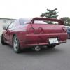
91 r32 just came off the dyno

rb25det

t3/t04e

supporting fueling modifications

we are hitting a ceiling at 160rwkw at 5psi. ran up to 12psi and pulled all timing back and no change in power output

engine sounds fine on the headphones, air fuel ratios are safe, we have fuel for more power even at base pressure. turbo responds like a mid sized t3/t4 hybrid - positive pressure around 3000rpm, no weird noises

took a pressure reading from after the turbo, and also at the manifold - exactly the same power curve so we don't think it is a restriction in the intake/intercooler piping

airflow meter (z32) output voltage ramps up quickly with boost and then holds static voltage from there (with increasing rpm and boost).

the exhaust came with the car - I am thinking a collapsed muffler (baffles) or something??? it is 3.5" all the way through with one resonator and a rear super dragger muffler, but it is quite quiet

has anyone else run into similar issues before? could it be any other part of my system?

Given it's a 10min job to drop the exhaust and do a run, surprised you didn't to rule it out as an issue if you went to the effort of testing the pressure.

BUT... you tested the pressure, so you would know if it was a problem or not... So what were the results of that test? Was it overtly pressurised?

Either that or cam timing/belt is out a tooth. Seems fairly common that one.

while the problem was being diagnosed, the turbo oil feed line had a minor split and so we shut it down - didn't want to pull any power runs until we sorted that out since a major failure on the pressure side of the oil system would mean dead engine real quick.

we only took pressure values from the intake side, from the nipple right after the turbo compressor housing, and again at the inlet manifold. pressure readings were the same at both locations

I'm getting the oil line sorted shortly and just wanted to hear any opinions before I started down the road of figuring out this problem

we pulled the timing right back while trying to diagnose on the dyno with no change to the power output - surely if the belt was off we would have seen some changes there?

Edited by clip14

Cat has been removed - exhaust set up is as follows

factory exhaust manifold

38mm gate taken off the manifold before the turbo

custom downpipe with external gate plumbed back in

no cat

3.5" exhaust with one resonator and one rear muffler (installed prior to purchasing car).

we pulled the timing right back while trying to diagnose on the dyno with no change to the power output - surely if the belt was off we would have seen some changes there?

Belt is for cam timing. You were adjusting ignition timing

Cat has been removed - exhaust set up is as follows

factory exhaust manifold

38mm gate taken off the manifold before the turbo

custom downpipe with external gate plumbed back in

no cat

3.5" exhaust with one resonator and one rear muffler (installed prior to purchasing car).

I'd still be dropping the exhaust and doing a run/two to rule it out.

Very common for Jap exhausts to have 2.5" restrictors welded in before/after resonators/mufflers etc.

My rear super dragger muffler was all rusted and colapsed on the inside. They're a fairly old muffler I think. Ended up gutting it.

the muffler is not in great condition - will replace it this weekend. cheers

Belt is for cam timing. You were adjusting ignition timing

right, sorry about that. i had a chat with my tuner, he says he played around with the vct and it didnt look like there was a problem there. He will check the cam timing before it goes back onto the dyno.

I'd still be dropping the exhaust and doing a run/two to rule it out.

Very common for Jap exhausts to have 2.5" restrictors welded in before/after resonators/mufflers etc.

will be dropping the entire exhaust and making sure it is alright - most likely will just get a new rear section rebuilt to be sure.

165 is also around the max a faulty cas makes, did the curve go wavy? look at exhaust first.

I dont have the output from the previous dyno runs on hand. what do you mean by wavy? which curve?

Is there any other way to troubleshoot a faulty CAS?

Thanks everyone for their responses!!

Edited by clip14

I dont have the output from the previous dyno runs on hand. what do you mean by wavy? which curve?

Is there any other way to troubleshoot a faulty CAS?

Meaning as it was on the dyno was the readout on the screen wavy? Going up and down as power rose. Or was it a smooth steady line?

Create an account or sign in to comment

You need to be a member in order to leave a comment

Create an account

Sign up for a new account in our community. It's easy!

Register a new account

Sign in

Already have an account? Sign in here.

Sign In Now


  • Similar Content

  • Latest Posts

    • For once a good news  It needed to be adjusted by that one nut and it is ok  At least something was easy But thank you very much for help. But a small issue is now(gearbox) that when the car is stationary you can hear "clinking" from gearbox so some of the bearing is 100% not that happy... It goes away once you push clutch so it is 100% gearbox. Just if you know...what that bearing could be? It sounding like "spun bearing" but it is louder.
    • Yeah, that's fine**. But the numbers you came up with are just wrong. Try it for yourself. Put in any voltage from the possible range and see what result you get. You get nonsense. ** When I say "fine", I mean, it's still shit. The very simple linear formula (slope & intercept) is shit for a sensor with a non-linear response. This is the curve, from your data above. Look at the CURVE! It's only really linear between about 30 and 90 °C. And if you used only that range to define a curve, it would be great. But you would go more and more wrong as you went to higher temps. And that is why the slope & intercept found when you use 50 and 150 as the end points is so bad halfway between those points. The real curve is a long way below the linear curve which just zips straight between the end points, like this one. You could probably use the same slope and a lower intercept, to move that straight line down, and spread the error out. But you would 5-10°C off in a lot of places. You'd need to say what temperature range you really wanted to be most right - say, 100 to 130, and plop the line closest to teh real curve in that region, which would make it quite wrong down at the lower temperatures. Let me just say that HPTuners are not being realistic in only allowing for a simple linear curve. 
    • I feel I should re-iterate. The above picture is the only option available in the software and the blurb from HP Tuners I quoted earlier is the only way to add data to it and that's the description they offer as to how to figure it out. The only fields available is the blank box after (Input/ ) and the box right before = Output. Those are the only numbers that can be entered.
    • No, your formula is arse backwards. Mine is totally different to yours, and is the one I said was bang on at 50 and 150. I'll put your data into Excel (actually it already is, chart it and fit a linear fit to it, aiming to make it evenly wrong across the whole span. But not now. Other things to do first.
    • God damnit. The only option I actually have in the software is the one that is screenshotted. I am glad that I at least got it right... for those two points. Would it actually change anything if I chose/used 80C and 120C as the two points instead? My brain wants to imagine the formula put into HPtuners would be the same equation, otherwise none of this makes sense to me, unless: 1) The formula you put into VCM Scanner/HPTuners is always linear 2) The two points/input pairs are only arbitrary to choose (as the documentation implies) IF the actual scaling of the sensor is linear. then 3) If the scaling is not linear, the two points you choose matter a great deal, because the formula will draw a line between those two points only.
×
×
  • Create New...