Jump to content
SAU Community

Recommended Posts

Yeah ... money, money, money ...all going into that big black hole!!

But I'm not giving up, it will be sorted out... I'm in my mid 40s and if I do not get this project finished and the car running to its potential then I might just throw in the towel. :(

Latest update...

- The Holinger will not be delivered until mid - late July. Has anyone got a spare gearbox to loan me for a couple track days? I promise (fingers crossed) I won't break it.

- Electric Power Steering pump installed and will get wired up into the Motec PDM.

- I'm replacing the Odyssey with a Lithium battery (its due to die soon)

- I'm looking at installing the adjustable Ikeya lower control arms

It's been close to 18 months and I still have not had a decent drive in the car yet...

I'm not sure if I am going to put in an entry form for Superlap this year ...

Send me a Pm if your interested. It took a bit to get right and Im a sparky. Couldnt find much info off the net. But i think ive got it right now. Taken the car out now a few weekends now and no probs. Good mod in my opinion.

  • 3 weeks later...

Update:

- Astra Power steering pump installed by UAS using standard astra fuse/relay but is not setup with PDM yet. Will be hooked up properly in the next week or two by my motec guy.

- Holinger sent an email... box should be ready late June/early July... fingers crossed it turns up sooner rather than later.

- Rear lower control arms fitted by UAS, waiting for front Ikeya arms to arrive.

- Application to WTAC PRO-AM class was successful.

Now I need to get serious with getting myself ready for the challenge... need to lose another 10 kgs, sort out the right knee and get in some sort of shape (other than round).

It's gonna be fun!

  • 1 month later...

Received confirmation that the holinger should be delivered this week... hopefully it will be installed and be drivable again next week.

Now I need to get the wheel alignment sorted to a starting point, finish off some wiring and then get the car down to Tunehouse to check the tune and give it a tweak then off to get a feel for it around Sydney Motorsport Park...

Should be interesting!!

  • 4 weeks later...

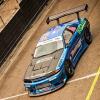
Thought you guys might be interested in the latest on the Tunehouse R32 GTR. We recently have been doing final mechanical work, check ups and dyno tuning.

We held a photo shoot last week, the photos have been posted up on WorldTimeAttack.com with specs of the car:

http://www.worldtimeattack.com/index.php/the-open-class-skyline-army-gets-a-new-recruit-with-the-tunehouse-r32-gtr/

article_pap7.jpg

article_pap9.jpg

The machine hit the hub dyno on Saturday to be tuned by Tunehouse owner Jim. Comfortably and efficiently we made 500 AWKW @ 16 PSI, looking to go up to 25 PSI in the future.

GTRDyno.jpg

With the tune done, the keys (so to speak) were handed over to John Boston last Sunday for a shakedown and test lap. You can check out his in cabin camera footage here:

https://www.facebook.com/photo.php?v=10201592045342138

And another of it moving out of the pits:

https://www.facebook.com/photo.php?v=10201588104603622

There are some minor enhancements to with fuel and oil pressure, but working out the kinks is to be expected of course.

The car is being entered into the open class @ WTAC this year and we are keen to see what it can do.

We'll keep you guys posted!

Tunehouse

It's certainly making the numbers, hopefully you can get it set up to put power to the ground.

Let's have a closer look at the aero please.

More detail around the splitter/undertray, and the rear wing + diffuser section would be great.

Sorry about the footage guys, the videos are hosted on somebody's personal account.

The aero and diffuser work is all custom, unfortunately there's not much more I can tell you than that.

Tunehouse

Boost level is consistent, our hub dyno picks up every little twitch in the output.

I know how a hub dyno works, you should be making peak torque at around 5000-5500rpm not 7500rpm. Something is causing you to lose a lot of mid range power?

PS. How do the RB20 Nics covers go with blow bye?

Edited by SimonR32

The aero and diffuser work is all custom, unfortunately there's not much more I can tell you than that.

Any chance you might post up some pictures? That was the detail I was referring to, wanted a look if possible.

Create an account or sign in to comment

You need to be a member in order to leave a comment

Create an account

Sign up for a new account in our community. It's easy!

Register a new account

Sign in

Already have an account? Sign in here.

Sign In Now


  • Similar Content

  • Latest Posts

    • Yeah, that's fine**. But the numbers you came up with are just wrong. Try it for yourself. Put in any voltage from the possible range and see what result you get. You get nonsense. ** When I say "fine", I mean, it's still shit. The very simple linear formula (slope & intercept) is shit for a sensor with a non-linear response. This is the curve, from your data above. Look at the CURVE! It's only really linear between about 30 and 90 °C. And if you used only that range to define a curve, it would be great. But you would go more and more wrong as you went to higher temps. And that is why the slope & intercept found when you use 50 and 150 as the end points is so bad halfway between those points. The real curve is a long way below the linear curve which just zips straight between the end points, like this one. You could probably use the same slope and a lower intercept, to move that straight line down, and spread the error out. But you would 5-10°C off in a lot of places. You'd need to say what temperature range you really wanted to be most right - say, 100 to 130, and plop the line closest to teh real curve in that region, which would make it quite wrong down at the lower temperatures. Let me just say that HPTuners are not being realistic in only allowing for a simple linear curve. 
    • I feel I should re-iterate. The above picture is the only option available in the software and the blurb from HP Tuners I quoted earlier is the only way to add data to it and that's the description they offer as to how to figure it out. The only fields available is the blank box after (Input/ ) and the box right before = Output. Those are the only numbers that can be entered.
    • No, your formula is arse backwards. Mine is totally different to yours, and is the one I said was bang on at 50 and 150. I'll put your data into Excel (actually it already is, chart it and fit a linear fit to it, aiming to make it evenly wrong across the whole span. But not now. Other things to do first.
    • God damnit. The only option I actually have in the software is the one that is screenshotted. I am glad that I at least got it right... for those two points. Would it actually change anything if I chose/used 80C and 120C as the two points instead? My brain wants to imagine the formula put into HPtuners would be the same equation, otherwise none of this makes sense to me, unless: 1) The formula you put into VCM Scanner/HPTuners is always linear 2) The two points/input pairs are only arbitrary to choose (as the documentation implies) IF the actual scaling of the sensor is linear. then 3) If the scaling is not linear, the two points you choose matter a great deal, because the formula will draw a line between those two points only.
    • Nah, that is hella wrong. If I do a simple linear between 150°C (0.407v) and 50°C (2.98v) I get the formula Temperature = -38.8651*voltage + 165.8181 It is perfectly correct at 50 and 150, but it is as much as 20° out in the region of 110°C, because the actual data is significantly non-linear there. It is no more than 4° out down at the lowest temperatures, but is is seriously shit almost everywhere. I cannot believe that the instruction is to do a 2 point linear fit. I would say the method I used previously would have to be better.
×
×
  • Create New...