Jump to content
SAU Community

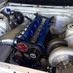
My Breather Setup


edizio
 Share

Recommended Posts

Your explanation of the PCV is making sense to me; however in this scenario, wouldn't the PCV still be closed even though the crankcase is under positive pressure: -

It depends on how much negative pressure the Venturi system is creating and how much positive pressure is in the intake, as soon as there is boost in the intake the PCV closes and the gases are meant to go to the I take of the turbo

[\quote] I'm driving hard on boost - Positive pressure in crank case causing the PCV, negative pressure from the venturi in the pipe leading to the valve. In this scenario, I would expect the valve to be shut but shouldn't it be open to vent the crank case so that the blow by isn't just venting out of the catch tank - it obviously has no where else to go does it?

That's right, the positive crankcase pressure should be getting sucked out by the Venturi since the is boost pressure in the I take manifold it can not go in there as the boost pressure will cause the PVC to close

[\quote]So, I then take my foot off the gas and theoretically I should be in a vacuum/negative but the crankcase won't have vented because it has no where to go so. I then have very little suction (well a little bit), from the venturi port and still positive pressure which means the port is still closed...

This is when the PVC will open and draws gases away from the cam covers pulling gas out of the crank case, the PVC is controlled by the intake manifold unless the Venturi system is creating a higher vacuum level

[\quote]

This is what I don't understand

This is the PCV valve that the venturi port connects to:

rb26dett_pcv_valve_1.JPG

Now, I see that in some race car setups, they actually have a vacuum pump; even in this scenario, isn't the PCV still always just closed?

The Venturi connects to the exhaust side cam cover, the PCV connects to the intake side cam cover and the two covers are connected to each other but both have the volume of cam covers and head and well crank case to draw from effectively separating them from each other

The crank case should never be in negative pressure with out external help as even at idle there is blowby just not much

The vacuum pumps that race cars have is because they are using stupidly long duration cams and have lost the intake vacuum in doing so so they have to create it somehow, which should not be connected through the PCV as it would just cause it to close

Link to comment
Share on other sites

Okay right, so I have custom intake and exhaust cams on this car! (TODA 264 9.3mm).

Currently with the operation of the PCV valve though, if the positive pressure inside the crankcase is higher, the valve remains shut? because that's currently what happens if I simulate the effect by blowing on the side with the screw

Link to comment
Share on other sites

The PCV screws in to the balance tube on the intake manifold so the threaded end is seeing what ever the intake manifold is doing

So vacuum created by shutting the throttle bodies opens the valve and when the throttle bodies are open and boost is going into the intake manifold it closes the valve :thumbsup:

264s are not stupidly long duration, 280+ is getting stupidly long :(

Who does your tuning and what ECU have you got ?

Link to comment
Share on other sites

Hey,

So, this is where the PCV is connected to; straight off the end of the black pipe that comes from the intake cam breather. I thought that's the valve cover not the intake manifold.

EyQU6DZ.jpg

I have an Apexi Power FC ECU; I do a lot of the tuning myself and with the original owner but I'm ok with the tuning aspect; I built my own det cans and have the AFRs at 11.5 on boost with 12 coming on to boost. I run idle at around 13.9 as the cams don't take idling at 14.7. The ignition timing is a bit more convoluted to explain but that should be good too. The CAS is set by the original owner and I haven't touched that and the boost controller is a greddy protecB that I manage the boost with.

Link to comment
Share on other sites

So when on full boost if the pcv will close, the venturi system is closed because of positive pressure from the exhaust, where is the positive crankcase pressure going, only way out is through the dipstick isn't it?

  • Like 1
Link to comment
Share on other sites

We use venturies on our mining equipment to vac out the dust collectors on the air filter box's, but the actual venturi pipe is located just inside the tip of the exhaust, so as the gas expands out it creates a negative at the end of the vac pipe,

It took quite a bit of trial and error to find the perfect distance from the tip, but it wont inside the exhaust near the turbo with that much pipe left!

  • Like 1
Link to comment
Share on other sites

Lol! yeah quite correct... it did work kinda but if your oil air seperator isn't up to the task you just draw through oil vapour and make a nice smokey exhaust. i still have one connected....but my issue was not ventilating enough i.e venting through a size smaller than the two 5/8 vents off the cam covers effectively pressurizing my catch can.

Link to comment
Share on other sites

Xgtrx, no, positive pressure from the exhaust never reaches the PCV because of the one way valve. My original post shows the valve that stops any exhaust gases travelling back up.

If exhaust gases were getting up, they would actually open the PCV valve which is what I don't really understand and I the opposite case of what I've been asking about

Link to comment
Share on other sites

Yeah but if both valves are closed when the car is on boost, where is the positive crankcase pressure going, the only way out is through the dipstick, yes? It can't be scavenged through the exhaust because the exhaust gasses would causing positive pressure compared to the crankcase. Or have I got this totally wrong?

Link to comment
Share on other sites

That is correct except for the reasoning behind why the gases aren't being sucked out. They aren't being sucked out because any suction closes the PCV valve, which surely can't be right?? and I believe that's why oil is going out the dipstickbut I can't understand why someone clever enough to build an engine and set up all the timings etc would fit a Venturi to a valve that never releases any positive pressure from the crankcase. It seems to me like if a Venturi is being used, then a PCV valve is not the correct valve to use.

I am not advocating for or against the use of Venturi to create negative pressure, nor am I saying I will keep this solution, but if this setup, in theory, were supposed to work, how would having a PCV valve connected do anything if it only opens on positive pressure from the exhaust side, for which there never will be any because of the one way valve not allowing any exhaust gases through. The tube that connects to the PCV in this setup is always under vacuum. The Venturi is creating good suction at idle and even more as the rpm increases which implies to me that all PCV valve will never be open.

Link to comment
Share on other sites

Your thinking to big picture and in this case that's not how to do it

What you have is two differential valves, one is controlled by the intake manifold and the other is controlled by the exhaust pipe and while in theory this should work the practical side of mean both valves shut at the same time

The intake one closes as soon as the throttle opens, when the throttle is open the exhaust gas increases to the point there is backpressure which closes the exhaust side one

now this is where you need to read carefully, while there is more pressure on the outside of the valves then the inside they remain closed so the crankcase is building pressure from blowby which is lower then the intake pressure and exhaust back pressure it has nowhere to go except out the dip stick tube

What you need to find out is what the Venturi is doing at full noise when the exhaust back pressure is at its highest and the motor has full boost level

  • Like 1
Link to comment
Share on other sites

Xklaba, starting to understand I think.. Although I can't imagine that much back pressure. It is 4" all the way through to a tiny back box and doesn't have any cats.

Maybe I'm still a little confused but am I wrong in thinking that the gases should be escaping through the PCV valve?

Link to comment
Share on other sites

No full exhaust system is going to have zero back pressure no matter how free flowing it is. The exhaust is being pushed into the exhaust pipe.

Edited by Ben C34
Link to comment
Share on other sites

No exhaust is going to have zero back pressure no matter how fee flowing it is. The exhaust is being pushed into the exhaust pipe.

I have to disagree with that, an old mate of mine had an exhaust that was 3" dia and 4" in lenght with seperate screamer pipe on his turbo R1 :D

Link to comment
Share on other sites

I have to disagree with that, an old mate of mine had an exhaust that was 3" dia and 4" in lenght with seperate screamer pipe on his turbo R1 :D

Yep. You managed to quote me before I edited!

Link to comment
Share on other sites

Create an account or sign in to comment

You need to be a member in order to leave a comment

Create an account

Sign up for a new account in our community. It's easy!

Register a new account

Sign in

Already have an account? Sign in here.

Sign In Now
 Share


  • Similar Content

  • Latest Posts

    • A31 is pretty much the same thing without HiAIDS I mean CAS, no improvement lol. Not to late to send it.
    • Thanks for all the replies! I also wanted to ask if wheels that were fitted on Ford Falcons would fit the 350GTs as well? In the area I'm at there aren't that many options for secondhand wheels and new ones here are way out of my budget. From what I've seen, most of the wheels that are available that were fitted on Ford Falcons have an offset of +33 to +36, with a centre bore of 70.5mm whereas the stock 350GT's ones are 66mm, can't seem to find any hubcentric rings that fit that difference though. 
    • 215/45/18 tyres are probably a little on the low side compared to the factory tyre, it should be closer to a 245/45/19, which will get you about an extra 11mm of height, and should make you speedo read a bit closer to reality. 245/45/19s will be a bit too far the other way and you risk a speeding ticket as your speedo might read slower than your actual speed.  245/40/19s would be correct if you are going to 19in rims, they will give you a similar total diameter to the 245/45/18 tyres.  
    • That's something I forgot to put in my list. The aggressive anti-squat in R32 is a f**king menace. I still need to decide if I'm going to drag the subframe out of my car and weld in the GKTech corrector kit. The main reason to dither is the need to switch to spherical joints in the lower arm to account for the twist induced in the rear pivot caused by lowering the front pivot. And yes...we do put better subframes in R32s, and I wish I'd gotten an S14 one instead of an A31 when I did the "take off and nuke it from orbit" HICAS delete all those years ago.
    • I have been looking at some setting on the alarms for the Q60 and what buttons do and so and also been looking for details on the alarm in my V37 which is a standard issue with the car. settings like window roll up and a few others seem to not work at all. i cant seem to find exact info on V37 alarms so Q60 is all i can really go off i have not tried 400Z alarm settings or info yet so that will be next. any one got like a sheet of info on the alarm system in the V37 as all my documents are in japanese but i thought the system would basically be like standard through similar models? 
×
×
  • Create New...