Jump to content
SAU Community

Recommended Posts

Advice / Input

Hey Guys i'm new to the forum and need some help if you don't mind.:banana: I live in South Africa

I currently have an Rb 25 Det lemme give quick run down on spec's.

Sub Assembly skimmed 1 mm Rb 26 pistons 86 mm COMETIC Head Gasket

Head done ported and gas flowed cams cut 270. Done by Steve Clark No Sweat Racing

Head currently has all Rb 26 parts , Valves , Quarters , Retainers , Valve Springs , Lifters etc. So Head is Solid Cams and Lifters. Head can probably rev about 8500rpm+ but oil pump is stock.

Branch build by Marius from Full Boost 3 into 2 into 1.

Turbo Garret 60-1 T4

Bosch 750 cc Injectors

Bosch 044 external and Facet in tank pump

Rb 30 Clutch and Pressure Plate

40 mm Wastegate

Custom Intake Manifold

Intercooler

Spitronics Engine Management 60-2

70 mm Exhaust

Currently has 1 Bar map on 95 ctane pump fuel. Took the car for Dyno but was spark breaking on the Dyno will replace this weekend.

Not sure if any of you have similar set ups. So this is where I need some info please car will be going back to Dyno soon:happy:

I will be Changing Fuel to 50/50 95/Ethanol

What do you guys thinjk Rb 26 pistons can take max boost?

I'm looking to try and push for 1.2-1.5 bar boost is this ok?

What Hp should I aim for safely?

If you guys can assist with any input will be highly appreciated. Sorry about the book tried to give as much info as I can:cool:

Thanks

Brian

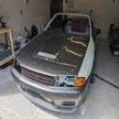
16012014321.jpg

16012014323.jpg

IMG-20140207-00454.jpg

IMG-20140207-00455.jpg

  • Like 1
Link to comment
https://www.sau.com.au/forums/topic/470997-advice-input/
Share on other sites

Hi thanks man. It is a 1972 Chevrolet 4.1 Limited manufactured in SA and Australia also had them.

Awesome, I'm not a huge muscle car guy so would never have managed to guess. I hope someone here can give you some guidance. :)
Link to comment
https://www.sau.com.au/forums/topic/470997-advice-input/#findComment-7836682
Share on other sites

Thanks and I hope they will assist me. Unfortunately had to do mod in there because they never brought R32,33,34 to SA. We can only buy the engine's here or import the car which is very expensive. I would like to own a R34 Gtr Vspec though:banana::banana:

  • Like 1
Link to comment
https://www.sau.com.au/forums/topic/470997-advice-input/#findComment-7836684
Share on other sites

1.5 bar is nothing - do not go by numbers - your tuner should keep increasing boost until it becomes counter productive and similarly tune to max with regard to exhaust temps knock control etc. You will get what you get.

Link to comment
https://www.sau.com.au/forums/topic/470997-advice-input/#findComment-7837240
Share on other sites

Hi Kiwi I've been busy with converting a set of coils but came across another thread discussing some of the issues other guys are having. After reading through It seems to me that I may have a similar problem. So I removed all the coils including the aluminum portion that is bolted in the middle of the cylinder head. Low and behold the hole bottom of the aluminum casing is black seems that the coils have been earthing against it when ever it spark breaks. So my car starts normal idles normal and rev up to limit when stationery also is not missing like a dead plug or coil. Only time it spark breaks it under load. So I got some liquid electrical tape with a brush and also bought some plastidip spray also for electrical insulation. I will be spraying the aluminum cover with that to insulate it so the coils does not spark against it. Also will do the coils and suppressors with the other. Worth the try I guess. I unfortunately cannot have the aluminum portion cnc'd out of plastic as the other guys did. So I will be doing that tonight possibly with put everything back tomorrow and go and test. Hopefully resolves my issue if not I have been busy with a set of other coils. Don't know if you've seen any of the threads speaking about spark break issues.

Link to comment
https://www.sau.com.au/forums/topic/470997-advice-input/#findComment-7838250
Share on other sites

1 hour ago, Chev R said:

. Don't know if you've seen any of the threads speaking about spark break issues.

Yes there are hundreds of such threads. Your fix may work for a while (gap your plugs down to 0.8mm as well) but start saving for some new coils.

Link to comment
https://www.sau.com.au/forums/topic/470997-advice-input/#findComment-7838265
Share on other sites

Create an account or sign in to comment

You need to be a member in order to leave a comment

Create an account

Sign up for a new account in our community. It's easy!

Register a new account

Sign in

Already have an account? Sign in here.

Sign In Now


  • Similar Content

  • Latest Posts

    • For once a good news  It needed to be adjusted by that one nut and it is ok  At least something was easy But thank you very much for help. But a small issue is now(gearbox) that when the car is stationary you can hear "clinking" from gearbox so some of the bearing is 100% not that happy... It goes away once you push clutch so it is 100% gearbox. Just if you know...what that bearing could be? It sounding like "spun bearing" but it is louder.
    • Yeah, that's fine**. But the numbers you came up with are just wrong. Try it for yourself. Put in any voltage from the possible range and see what result you get. You get nonsense. ** When I say "fine", I mean, it's still shit. The very simple linear formula (slope & intercept) is shit for a sensor with a non-linear response. This is the curve, from your data above. Look at the CURVE! It's only really linear between about 30 and 90 °C. And if you used only that range to define a curve, it would be great. But you would go more and more wrong as you went to higher temps. And that is why the slope & intercept found when you use 50 and 150 as the end points is so bad halfway between those points. The real curve is a long way below the linear curve which just zips straight between the end points, like this one. You could probably use the same slope and a lower intercept, to move that straight line down, and spread the error out. But you would 5-10°C off in a lot of places. You'd need to say what temperature range you really wanted to be most right - say, 100 to 130, and plop the line closest to teh real curve in that region, which would make it quite wrong down at the lower temperatures. Let me just say that HPTuners are not being realistic in only allowing for a simple linear curve. 
    • I feel I should re-iterate. The above picture is the only option available in the software and the blurb from HP Tuners I quoted earlier is the only way to add data to it and that's the description they offer as to how to figure it out. The only fields available is the blank box after (Input/ ) and the box right before = Output. Those are the only numbers that can be entered.
    • No, your formula is arse backwards. Mine is totally different to yours, and is the one I said was bang on at 50 and 150. I'll put your data into Excel (actually it already is, chart it and fit a linear fit to it, aiming to make it evenly wrong across the whole span. But not now. Other things to do first.
    • God damnit. The only option I actually have in the software is the one that is screenshotted. I am glad that I at least got it right... for those two points. Would it actually change anything if I chose/used 80C and 120C as the two points instead? My brain wants to imagine the formula put into HPtuners would be the same equation, otherwise none of this makes sense to me, unless: 1) The formula you put into VCM Scanner/HPTuners is always linear 2) The two points/input pairs are only arbitrary to choose (as the documentation implies) IF the actual scaling of the sensor is linear. then 3) If the scaling is not linear, the two points you choose matter a great deal, because the formula will draw a line between those two points only.
×
×
  • Create New...