Jump to content
SAU Community

Recommended Posts

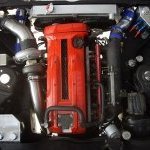
I spent a couple of hours on the dyno spead out over a couple of nights. I have been using the power FC software which has enabled me to tune sooo much more easily.

Mods.

87mm CP pistons

Tomei poncams 260 9.15

1mm oversize valves

HKS2530's with modified exhaust port to match chinese stainless manifolds

ARC twin entry intercooler

Blanked off BOV's (came with ARC cooler kit)

Mines AFM's

GTR+044 and surge tank

Nismo Fuel Pressure Reg

Apexi pod filters

Just Jap Alloy Radiator

Greddy cam gears

2x3" exhaust with 2x magic cats into a single 3.5

I also played with both cam timings and found 0 degrees to be optimal, I could get more power up top with 4+ degrees on the exhaust but at the expense of low down power.

comments welcome

post-2338-1160639114.jpg

Link to comment
https://www.sau.com.au/forums/topic/138408-tuneddynod-my-gtr/
Share on other sites

Comment: Pull that temp sensor out of the engine bay and do another run without corrections :P

Anyways, good power and a reasonable curve.

Spend a bit more time to eliminate that dip in the mid range and it'll be near on perfect!!

Was that around 20-22psi mark?

Haha, well spotted :D

Comment: Pull that temp sensor out of the engine bay and do another run without corrections :P

Anyways, good power and a reasonable curve.

Spend a bit more time to eliminate that dip in the mid range and it'll be near on perfect!!

Was that around 20-22psi mark?

Comment: Pull that temp sensor out of the engine bay and do another run without corrections :P

Anyways, good power and a reasonable curve.

Spend a bit more time to eliminate that dip in the mid range and it'll be near on perfect!!

Was that around 20-22psi mark?

yeah the temp was right up there, i had my pod shield out which definately didn't help much. the AFR was rich reflecting how hot the water temp was. I also have another graph with the IT at 39 degrees with 378kw. the dip was wheel spin

spot on 21.5psi

For the record I agree the temp shouldn't be that high, the sensor was sitting under the pods against the metal of the car so I'm guess was hotter than it should have been, I would have estimated the IT at the time to have been 54ish degrees from what the PFC was telling me. any who 278rwkw with 39degrees IT, I can post up if u would like.

Edited by BOOSTD
Nice result matt, looks like a nice safe tune too 11.2 AFRs

have to catch up with you to have a look, last time i saw her there wasnt much in the engine bay :P

Yep she's coming along, The AFR's were tuned earlier in the night for 11.4 but this was a pretty warm run. I'd done a few 24psi runs just previous but the plugs let me down.

Lots of power is nice. :P

Since you did it yourself would you mind posting up some raw data? I'm particularly interested in how much advance you are running across the rev range.

What is base timing set to?

What rpm are you seeing full boost? 1 bar?

Thanks.

Advance is 18degrees max a full load base is 20, i'll have to check where 1 bar is

I do have some pics somewhere, the manifolds are heat wrapped and also the front pipes which extends behind the front seats

I have no idea what 6 or 6f is, I didn't setup the computer....=) haven't learnt that much as yet, hard enough remembering to turn the ramp up off in time after a power run so I don't get lines all over my graph lol The just jap radiator cools very well, it did leak from the cap for a month or so but has sealed up now.

Edited by BOOSTD

Wheelspin? :rant:

Get it strapped better and do a run :(

That will sort the dip out, did you get any runs without spin?

Although the AFR's are rich so if it was fully loaded up it probably wouldnt be a large issue.

21.5psi :) smack on what it should be for the 360-380 marker

Just hang the sensor on the dyno rack, good enough :rant:

while im aware most would have seen this, those that havent need to see it!

The mines ultimate r34, what 2530's can really do.

It looks like they have this thing pulling hard from not much over 4grand, almost unbelievably quick to ~9grand redline, what a crazy powerband!!

does anyone know how much peak power the mines car makes?

Am i remembering correctly that this car is in Australia now?

Create an account or sign in to comment

You need to be a member in order to leave a comment

Create an account

Sign up for a new account in our community. It's easy!

Register a new account

Sign in

Already have an account? Sign in here.

Sign In Now


  • Similar Content

  • Latest Posts

    • Yeah, that's fine**. But the numbers you came up with are just wrong. Try it for yourself. Put in any voltage from the possible range and see what result you get. You get nonsense. ** When I say "fine", I mean, it's still shit. The very simple linear formula (slope & intercept) is shit for a sensor with a non-linear response. This is the curve, from your data above. Look at the CURVE! It's only really linear between about 30 and 90 °C. And if you used only that range to define a curve, it would be great. But you would go more and more wrong as you went to higher temps. And that is why the slope & intercept found when you use 50 and 150 as the end points is so bad halfway between those points. The real curve is a long way below the linear curve which just zips straight between the end points, like this one. You could probably use the same slope and a lower intercept, to move that straight line down, and spread the error out. But you would 5-10°C off in a lot of places. You'd need to say what temperature range you really wanted to be most right - say, 100 to 130, and plop the line closest to teh real curve in that region, which would make it quite wrong down at the lower temperatures. Let me just say that HPTuners are not being realistic in only allowing for a simple linear curve. 
    • I feel I should re-iterate. The above picture is the only option available in the software and the blurb from HP Tuners I quoted earlier is the only way to add data to it and that's the description they offer as to how to figure it out. The only fields available is the blank box after (Input/ ) and the box right before = Output. Those are the only numbers that can be entered.
    • No, your formula is arse backwards. Mine is totally different to yours, and is the one I said was bang on at 50 and 150. I'll put your data into Excel (actually it already is, chart it and fit a linear fit to it, aiming to make it evenly wrong across the whole span. But not now. Other things to do first.
    • God damnit. The only option I actually have in the software is the one that is screenshotted. I am glad that I at least got it right... for those two points. Would it actually change anything if I chose/used 80C and 120C as the two points instead? My brain wants to imagine the formula put into HPtuners would be the same equation, otherwise none of this makes sense to me, unless: 1) The formula you put into VCM Scanner/HPTuners is always linear 2) The two points/input pairs are only arbitrary to choose (as the documentation implies) IF the actual scaling of the sensor is linear. then 3) If the scaling is not linear, the two points you choose matter a great deal, because the formula will draw a line between those two points only.
    • Nah, that is hella wrong. If I do a simple linear between 150°C (0.407v) and 50°C (2.98v) I get the formula Temperature = -38.8651*voltage + 165.8181 It is perfectly correct at 50 and 150, but it is as much as 20° out in the region of 110°C, because the actual data is significantly non-linear there. It is no more than 4° out down at the lowest temperatures, but is is seriously shit almost everywhere. I cannot believe that the instruction is to do a 2 point linear fit. I would say the method I used previously would have to be better.
×
×
  • Create New...