Jump to content
SAU Community

Recommended Posts

Ooow I have a Synchronic 50mm Wastegate also, Let me know if you find somewhere local to get the brass fittings from I can't find anyone here in brisbane who has them.

What brass fittings are you talking about?

lol the ring that goes between the wastegate and manifold is copper... but the little brass air fittings I cannot find, as to use it with a AVCR etc. you need to link A and B ports together and seal the top hole to act as the top of the WG and then use C or D for the lower depending onf the boost level required

But with the Aud $ the way ti is getting a little brass fitting from Synapse will cost around $40 after conversion and shipping costs for somethign so small.

Ill be using C and D for my base boost level.

Have you tried taking it to Pirtek to see if they have anything that will fit?

from memory mine will only be using port D with some preload adjustment. afaik you just leave the ones you aren't using unblocked?

from memory mine will only be using port D with some preload adjustment. afaik you just leave the ones you aren't using unblocked?

Hmm, I was told by them to link A&B together to use As the top feed back to the acuator and then c or d as the bottom feed back to the acuator

What sort of base boost level were u getting? I am hoping to run 14psi, 20psi and 28psi with my new build

Hmm, I was told by them to link A&B together to use As the top feed back to the acuator and then c or d as the bottom feed back to the acuator

What sort of base boost level were u getting? I am hoping to run 14psi, 20psi and 28psi with my new build

Its not in yet, looking at 20-22 psi, using the 50mm valve seat, the 60lb spring. From what i got reading the manual that comes with it i should only need to use port D and some preload to achieve this (i wont be running an ebc i only want the one boost setting)

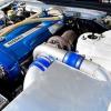
In my RB25 /T04z twin scroll w/ 100mm run offs to 50mm synchronic I run it like so:

Stiffest preload spring

A&B joined to my EVC6

C- boost

This gives me 13psi low boost and it is dead stable till 27psi, youll find that you have to run the offset right down, so you could in essence just use B for your boost controler or A depending on how much "gain" you want to run on the solonoid/stepper.

Fantastic WG, I use teflon lines with quick couplings so switching it around as I want is cake... but where it is now is perfect, 2nd gear is easy to hold straight at 13psi and as im into 3rd the evc gives me 19psi and 4th and 5th are 25 to 27psi.

Hmm I can't wait to hit high boost of 28psi :P

I hope you get yours back on the road by the end of the year Dave. After reading about your belt I didnt wait to change the tension on mine got straight too it, I'm using the same belt

In my RB25 /T04z twin scroll w/ 100mm run offs to 50mm synchronic I run it like so:

Stiffest preload spring

A&B joined to my EVC6

C- boost

This gives me 13psi low boost and it is dead stable till 27psi, youll find that you have to run the offset right down, so you could in essence just use B for your boost controler or A depending on how much "gain" you want to run on the solonoid/stepper.

Fantastic WG, I use teflon lines with quick couplings so switching it around as I want is cake... but where it is now is perfect, 2nd gear is easy to hold straight at 13psi and as im into 3rd the evc gives me 19psi and 4th and 5th are 25 to 27psi.

That sounds like an awesome setup. Stepping the boost up through the gears would give you great traction.

That sounds like an awesome setup. Stepping the boost up through the gears would give you great traction.

Yeah its set up to boost higher as speed increases, the boost controler was one of the best traction devices I ever purchased :-) , got the combo in an S14 so the power to weight is pretty high for a street car... The T04z on the other hand is pure love! in 2nd shes all in at 4200rpm and 3rd shes at 28psi by 4000rpm giving it a very strong 4000rpm long powerband. Far more pleasant/easier drive than when it was fitted with the GT35 .82,,, now just to pull off an AWD conversion.

Create an account or sign in to comment

You need to be a member in order to leave a comment

Create an account

Sign up for a new account in our community. It's easy!

Register a new account

Sign in

Already have an account? Sign in here.

Sign In Now


  • Similar Content

  • Latest Posts

    • Power is fed to the ECU when the ignition switch is switched to IGN, at terminal 58. That same wire also connects to the ECCS relay to provide both the coil power and the contact side. When the ECU sees power at 58 it switches 16 to earth, which pulls the ECCS relay on, which feeds main power into the ECU and also to a bunch of other things. None of this is directly involved in the fuel pump - it just has to happen first. The ECU will pull terminal 18 to earth when it wants the fuel pump to run. This allows the fuel pump relay to pull in, which switches power on into the rest of the fuel pump control equipment. The fuel pump control regulator is controlled from terminal 104 on the ECU and is switched high or low depending on whether the ECU thinks the pump needs to run high or low. (I don't know which way around that is, and it really doesn't matter right now). The fuel pump control reg is really just a resistor that controls how the power through the pump goes to earth. Either straight to earth, or via the resistor. This part doesn't matter much to us today. The power to the fuel pump relay comes from one of the switched wires from the IGN switch and fusebox that is not shown off to the left of this page. That power runs the fuel pump relay coil and a number of other engine peripherals. Those peripherals don't really matter. All that matters is that there should be power available at the relay when the key is in the right position. At least - I think it's switched. If it's not switched, then power will be there all the time. Either way, if you don't have power there when you need it (ie, key on) then it won't work. The input-output switching side of the relay gains its power from a line similar (but not the same as) the one that feeds the ECU. SO I presume that is switched. Again, if there is not power there when you need it, then you have to look upstream. And... the upshot of all that? There is no "ground" at the fuel pump relay. Where you say: and say that pin 1 Black/Pink is ground, that is not true. The ECU trigger is AF73, is black/pink, and is the "ground". When the ECU says it is. The Blue/White wire is the "constant" 12V to power the relay's coil. And when I say "constant", I mean it may well only be on when the key is on. As I said above. So, when the ECU says not to be running the pump (which is any time after about 3s of switching on, with no crank signal or engine speed yet), then you should see 12V at both 1 and 2. Because the 12V will be all the way up to the ECU terminal 18, waiting to be switched to ground. When the ECU switches the fuel pump on, then AF73 should go to ~0V, having been switched to ground and the voltage drop now occurring over the relay coil. 3 & 5 are easy. 5 is the other "constant" 12V, that may or may not be constant but will very much want to be there when the key is on. Same as above. 3 goes to the pump. There should never be 12V visible at 3 unless the relay is pulled in. As to where the immobiliser might have been spliced into all this.... It will either have to be on wire AF70 or AF71, whichever is most accessible near the alarm. Given that all those wires run from the engine bay fusebox or the ECU, via the driver's area to the rear of the car, it could really be either. AF70 will be the same colour from the appropriate fuse all the way to the pump. If it has been cut and is dangling, you should be able to see that  in that area somewhere. Same with AF71.   You really should be able to force the pump to run. Just jump 12V onto AF72 and it should go. That will prove that the pump itself is willing to go along with you when you sort out the upstream. You really should be able to force the fuel pump relay on. Just short AF73 to earth when the key is on. If the pump runs, then the relay is fine, and all the power up to both inputs on the relay is fine. If it doesn't run (and given that you checked the relay itself actually works) then one or both of AF70 and AF71 are not bringing power to the game.
    • @PranK can you elaborate further on the Colorlock Dye? The website has a lot of options. I'm sure you've done all the research. I have old genuine leather seats that I have bought various refurbing creams and such, but never a dye. Any info on how long it lasts? Does it wash out? Is it a hassle? What product do I actually need? Am I just buying this kit and following the steps the page advises or something else? https://www.colourlockaustralia.com.au/colourlock-leather-repair-kit-dye.html
    • These going to fit over the big brakes? I'd be reeeeeeeeaaaall hesitant to believe so.
    • The leather work properly stunned me. Again, I am thankful that the leather was in such good condition. I'm not sure what the indent is at the top of the passenger seat. Like somebody was sitting in it with a golf ball between their shoulders. The wheels are more grey than silver now and missing a lot of gloss.  Here's one with nice silver wheels.
    • It's amazing how well the works on the leather seats. Looks mint. Looking forward to see how you go with the wheels. They do suit the car! Gutter rash is easy to fix, but I'm curious about getting the colour done.
×
×
  • Create New...