Jump to content
SAU Community

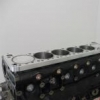
Rb34 / 24U (Rb26 + 800Cc) - Project RB high deck engine (and related builds)


Recommended Posts

I have been extremely busy the work that pays my bills lately, so the car had been sitting with a big box of parts next to it for way too long. But the past 2-3 weekends I've been able to give it some time.

The E85 fuel system is finished. I now have two in tank lift pumps and an external Holly 1800, all capable of around 600lt/hr. Injector wise I went with the bosch 1450cc. When run at 58psi they flow 1781cc, which will meet my power goal on E85. All fuel lines are now AN8.

I bought an IO expander for the Haltech and mounted it in the boot, so it is able to have short wiring to the flex fuel sensor (which is mounted inline with the overflow from the surge tank). I am also using the digital pulsed outputs to control fuel pump speed dynamically based on injector duty cycle. So far that appears to keep the pumps and fuel cold enough that I wont need to add a fuel cooler on the return line.

There is a couple more things to do to the car before it will be ready to hit the dyno. I have a new LSU4.9 wideband setup to put in the car and a little tidy up here and there.

I'm also gathering the last few pieces together for preparing 2 more bottom ends which will be going into R&D cars. Thats going to hopefully all come together over the next couple of months. Crankshaft machining starts in the next week or 2, and hopefully the blocks will be sleeved some time after that.

  • Like 1
Link to comment
Share on other sites

  • 1 month later...

Update Time!

Its been a long road to get here, but I finally have some test results for the engine. Last weekend Trent Whyte and Gordon Leonard from Mercury Motorsports jumped on a flight to tune my car and a few others at a workshop in Cairns.

It was a big weekend and nearly all the cars had problems that required some serious work to sort out. My car wasn't immune to this either.

Once a fuel system issue was sorted out the tuning began. Almost immediatly we encountered the next issue, which was that at the lowest boost level the engine was already exceeding the maximum torque for the clutch. Trent tried making the tune as soft as was possible, but it still refused to hold. In the end I had no option but to switch out the 18lb wastegate springs for a pair of 10lb springs.

The following day the car went back on the dyno. The clutch slipped initially but held once it was up to temp. Trent was able to finalise the tune and complete a 12lb wastegate tune on the car.

While not the huge success I was hoping for, we did see a glimpse of what the engine is capable of.

Here is the video :

Turn up your speakers - or if you prefer to think that stroker motors can't rev, then turn them off.

In the coming weeks I will be sourcing an NPC 1000hp twin plate carbon clutch, to replace the exeedy twin plate. Once done, Trent will be back to Cairns to complete the 18lb tune, and then crank up the boost with E85 race fuel.

That is all for now.

Edited by GTRNUR
  • Like 7
Link to comment
Share on other sites

All I can say to you Ian, is WOW !!!

Love the Vids. this one topped it spinning out the clutch is a bad but great thing. Bad got to upgrade the beast and great is high HP n torque at low end can't wait for next tune video keep them coming.

Inspiration for many.

And unleash that MONSTER!!!

Link to comment
Share on other sites

Great work Ian.

I know I have bugged you with questions before, but based on your R&D can you comment on steel sleeves in the RB26 whether they actually provide an improvement on block strength and rigidity or do they simply allow for a more 'consistent' bore in terms of geometry and metallurgy?

As an example, going out to a 88mm bore (or 90mm as you say is possible) in a sleeved block allows for 4.25mm wall thickness (88mm bore) or 3.25mm wall thickness (90mm bore). That doesn't take into account that there is original block material and sleeve material... how can such thin sections be justified? What analysis have you done to verify block integrity at high cylinder pressures and various other real life cases?

Really interesting stuff!

Link to comment
Share on other sites

Hi Mike,

I've had 3d modelling and FEA done on the sleeve design to indentify all weak points. I use different interference fits on the stepped sleeves at different heights in the block to eliminate weak area's, which results in those weak points being stronger than other areas that are thicker material. The spacer fitment and o-ring keying to the head help too.

Also consider that highest combustion cylinder pressures will occur within the top 30mm or so of the cylinder bore. This is in the thickest area of the exposed sleeved cylinder group, which becomes effectively solid where the sleeve passes through the deck of the block. As everything is interference fitted, there is no room for pressure induced expansion to distort a cylinder or induce a failure.

The weakest area of the sleeve is where its thinnest, at the bottom of the block. This area is also the most stable area of the factory block though due to being solid around the main bearing saddles, etc plus aided by partial block filling.

And yes, there is considerable porosity in blocks. There is a reason they say to not bore past 88mm, as the porosity and poorly cast metal in a factory N1 block begins to get sketchy at about 91mm, and at 92mm you are already breaking into water area's between cylinders and also low in the block around welsh plug height.

Link to comment
Share on other sites

Yes I remember you mentioned the stepped interference fits, that puzzles me a little... how many stepped interference fits do you have?

Yes, you are right about the cylinder pressure decreasing with increasing volume hence why the thickest section is at the top, etc.

Sorry for all the probing questions, but it is interesting and I am investigating whether something similar can be done to achieve a large bore RB26 (safely 88mm bore up to 90mm). I understand your sleeve design requires the spacer plate but something like this (follow link) could be done to achieve which I am talking about.

http://speedtalk.com/forum/viewtopic.php?f=1&t=43197&hilit=subaru

Link to comment
Share on other sites

All good Mike, if you ask a question I don't want to answer, I just wont answer it! :P

To be honest the risk in my design isn't the cylinder thickness. My main concern was if I had got the compression calculations correct for the gaskets either side of the spacer plate. Getting those wrong could have meant I'd pull the material that supports the studs right out of the block.

I don't think my sleeve design can be applied to a closed deck block to allow a bigger bore, as your risk then really does become the thinner bore thickness.

Considering your into coolant past 92mm when sleeving, to keep your bore thickness up you could only go to 95mm, but that is the maximum you can go to. As you would need at least 0.5mm of flange on the top to stop the sleeve slipping into the block. Resulting in 2.5mm of cylinder thickness with the 90mm bore, partially exposed to coolant once the piston passes below the deck. That is thinner than any un-supported cylinder in any engine I have researched. You would have a thin wall, as well as a thermal expansion induced stress concentration issue.

Link to comment
Share on other sites

Stick your finger down the front/left oil return on the block above the thermostat, and you will see the depth that the stud support goes to in the block. This is the reason a cnc machined in closed deck support plate will not work on an RB block.

The outer edges of the block and stud holes are supported by the deck of the block, which in turn is supported by the cylinders, attaching it to the material around the crank. If you machine out the entire deck of the block, the supporting material isn't there anymore.

The EJ257 block head studs go all the way down to the main stud material, so open deck blocks can be converted to closed deck with no problems at all.

I've had some thoughts about a Siamese cylinder option too. After thinking it through though its harder than what I have already done.

Link to comment
Share on other sites

All good Mike, if you ask a question I don't want to answer, I just wont answer it! :P

To be honest the risk in my design isn't the cylinder thickness. My main concern was if I had got the compression calculations correct for the gaskets either side of the spacer plate. Getting those wrong could have meant I'd pull the material that supports the studs right out of the block.

I don't think my sleeve design can be applied to a closed deck block to allow a bigger bore, as your risk then really does become the thinner bore thickness.

Considering your into coolant past 92mm when sleeving, to keep your bore thickness up you could only go to 95mm, but that is the maximum you can go to. As you would need at least 0.5mm of flange on the top to stop the sleeve slipping into the block. Resulting in 2.5mm of cylinder thickness with the 90mm bore, partially exposed to coolant once the piston passes below the deck. That is thinner than any un-supported cylinder in any engine I have researched. You would have a thin wall, as well as a thermal expansion induced stress concentration issue.

Yes I am with you now, thanks for the clarification. Will send you a PM.

Link to comment
Share on other sites

Create an account or sign in to comment

You need to be a member in order to leave a comment

Create an account

Sign up for a new account in our community. It's easy!

Register a new account

Sign in

Already have an account? Sign in here.

Sign In Now


×
×
  • Create New...