

Announcements
-
Similar Content
-
-
Latest Posts
-
 I want to also note I did lift the tire and checked for any play to see if it was a bad tie rod. It doesn't move at all.
 -
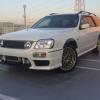
Any insight will help find the issue. When I do a sharp turn to the right I hear a screeching sound coming from the front. It only happens turning Right and not Left. Steering fluid seems okay. Not sure what this part is(picture) but one side seemed "wetter" than the other. All bushing from a quick look did not seem damaged. I'll do a better look but wanted to ask here in case it helps me troubleshoot faster.
-

-
 Nah. Was just wondering if you were having a small stroke or if there was some slur/gaf/inside joke that I wasn't aware of.
 -
That was a fark up, it's Salamanca Place I was thinking of. And now I'm curious as to what potential slur/gaf I have caused with Salamander Road, ha ha!
-


Recommended Posts
Create an account or sign in to comment
You need to be a member in order to leave a comment
Create an account
Sign up for a new account in our community. It's easy!
Register a new accountSign in
Already have an account? Sign in here.
Sign In Now