
Announcements
-
Similar Content
-
-
Latest Posts
-

By joshuaho96 · Posted
A lot of things we think of as recent are not that recent. Dead head to my knowledge was being done by the early 2000s for evaporative emissions reasons. CARB drove a lot of this with their PZEV requirements. -

-
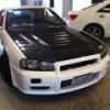
 Out with the lenso d1 18x10 +20 with 25mm spacers in with the ame 18x11plus 10 no spacers each rim and tyre was 8 kgs lighter lighter which should be noticeable Apprentice helped out
 -

-

-


Recommended Posts