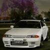
Jump to content
SAU Community

Recommended Posts

Yeah there were some... sacrifices made by Nissan to enable the twin turbo components to actually be removable in car, its not all ideal.

Got the turbo from GcG, they had one in stock so it was pretty easy. Manifold is going to be made up by a friend who is a fabricator.
Picked up a few other things over the last few weeks. Rebuilt starter motor, R33 A/C compressor and honeywell 0-150PSI pressure sensors for the oil and fuel systems. Will be getting the engine on Monday, stuff will be getting serious then!

Definate gains by sorting out that twin turbo pipe, Skidz. Sand the welds back and it would still looking factory :P.

Skidz it does!

Next time that pipe comes off I'll probably do it, so i can do a before and after logged comparison and if it does anything i should see the actual difference in fueling in the VE table.

Skidz it does!

Next time that pipe comes off I'll probably do it, so i can do a before and after logged comparison and if it does anything i should see the actual difference in fueling in the VE table.

There is a few good old videos around the traps about it. Even looking at it you can see the flaws in it. Doesn't take a rocket scientist to work that out.

A bloke in the states did a back to back. 8-12 HP extra across the graph IIRC.

There is a few good old videos around the traps about it. Even looking at it you can see the flaws in it. Doesn't take a rocket scientist to work that out.

A bloke in the states did a back to back. 8-12 HP extra across the graph IIRC.

Seen them n wasnt really convinced of anything tho.

I imagine air to follow a path of least resistance and I would think that the front turbo pressurising the second turbo would not be the path of least resistance.

Fuel tank out and exhaust off today, moved the car out and cleaned up, got the engine stand out. All ready for a special delivery tomorrow...

I'm going to miss this exhaust, seemed like a great performer and was good for noise, the full mid muffler may have something to do with that. Will have to crack it in half and have a squiz at the internal diameter later.

What are all you single turbo people doing for the turbo fluids? Oil intake should be easy, line from the block to turbo with correct fittings/elbows etc, ditto for water. Its the drains/returns i'm wondering about.

Oil wise as I understand use the front oil return, and block off the rear? braided return?

Water wise, the factory water return setup has a weird hardline combo that runs both to the water area at the rear of the block and also to the water return at the front of the block, I could tap it into that or just run a braided line to the front hardline?

Can't even see the best bits in that photo. Will probably help my dad do a rebuild once the car is back up and running, its getting pretty bad.

This week hopefully, got the whole week off so progress should be quicker

Started workign on under the plenum today, deleting the coolant and air lines that run around the back to the turbo plus the oil cooler lines. Used a RB20 water tap from the block instead of the split 26 one and got the ports on the water tube welded closed. Also removed the IAC as it was likely leaking and isn't required with the after market ECU, can just use the AAC for cold start.
All in all should be a lot less crowded down there... until I put the loom back in and i'm sure it'll look like a dogs breakfast again...

Also got my twin in tank fuel system done, pretty stoked with that, i'll grab some pictures tomorrow. Need to find some old hicas lines to use as fuel feed and return I think.

13551046_1072515919509165_557508458_n_zp

  • Like 3

Sorted out the under plenum pipework. Much much better.
Could have removed the unused fittings from the plenum and tapped+bunged them I suppose, but will just cap them and water inlet on the under runner water line. Retaining heater so now all I have is hot water out the block and the return.

P1150514_zpssvxnob2o.jpg

P1150522_zpsut0uh21z.jpg

Also as promised, pictures of the twin intank pump setup. I'm getting some Hicas lines (threw mine away, silly..) to use as hard lines for the fuel feed and return.

P1150517_zpsslcz1m09.jpg

P1150518_zpstaiiwcrs.jpg

P1150519_zpsnn346tsy.jpg

P1150521_zpssmx8vhuo.jpg

Also pissed off the BoV's and pipework. Some good weight reduction there...

P1150528_zpsxydnwd2i.jpgP1150529_zpsxvm8rcpp.jpg

Finally a mate was around and installed the LED high beams he'd been bugging me to do for ages. With these in and the HID's I should be able to do the mod to keep the low beams on with the highs, resulting in a much nicer amount of light at night.

P1150525_zps22o8hlrh.jpg

Unfortunately i've had a few hold ups...
Decided to throw the inspection camera in the sump just in case... And found 2 of the 3 trapdoors are stuck open. :unhappy:
The pickup doesn't really look good either, its on a ~15 degree angle from the bottom of the sump and around what looks to be 10mm from the bottom at the high end, from what I understand not really good enough. Also the oil pump wasn't notched enough for the crank trigger, so balancer will need to come off so I can attack it with a dremel. Literally only need to take 1mm of material off but its... frustrating. Also need to figure out how to actually fix the sensor in place, that's a bit of a mystery (cherry sensor). All in all, fun and games but a bit of a delay induced.

Also as promised, pictures of the twin intank pump setup. I'm getting some Hicas lines (threw mine away, silly..) to use as hard lines for the fuel feed and return.

P1150517_zpsslcz1m09.jpg

P1150518_zpstaiiwcrs.jpg

P1150519_zpsnn346tsy.jpg

P1150521_zpssmx8vhuo.jpg

WHOA! This in-tank setup is specific to the R32 I take it?! I like that. Had I seen it I would have done that.

EDIT - found their facebook page.

  • 4 months later...

Firstly, Apologies for the image quality jumping around, have been using different cameras and phones.

Secondly, Stuff has been happening but i've got about 5-6 updates worth of stuff to catch up to the present day, i'll write those over today/coming days.

Anyway, got to installing the Crank trigger and noticed the notch in the oil pump hadn't be lined up correctly.. fail.
Also there was no balancer bolt supplied by the engine shop. Miss communication there i guess, but was worrying they stuck the balancer on and didn't even mention it to me.

Yanked the balancer off and gave it a bit of a file for clearance. Got an ARP balancer bolt to hold it back on.

1467177058231.jpg


I also took the time to change out the streeting column bush while the engine was out. Wouldn't want to be doing it with the engine in at all. Old bushing was shot. Replaced it with a solid aluminum unit.

1467339516874.jpg

IMG_20160701_123214.jpg

IMG_20160701_123229.jpg


Before putting the engine in I decided to crack out the inspection camera and have a look into the engine... and had a bit of a shock. The oil pickup extension hadn't been installed correctly and the trapdoors were stuck on it: the sump had been installed upside down.
Anyway, had to take sump off, ended up making a jig and redoing pickup in correct orientation. After that put the sump back up... from underneath, which was entertaining to say the least...

IMG_20160725_135623.jpg

IMG_20160725_153500.jpg

IMG_20160728_191344.jpg

1469747735032.jpg

Finally i fixed up the results of a poor repair on a battery explosion done by a previous owner... well sort of fixed it

P1150532.JPG

P1150533.JPG


IMG_20160701_165250.jpg

P1150569.JPG

1469683187497.jpg


Possibly visible in the other update, but i've also removed all of the power steering lines. The R32 has a 2 rotor power steering pump, one for the rack itself and the second for the Hicas rack on the rear, which goes there via a solenoid in the front of the drivers side engine bay and then hard lines under the car to a second one at the back and returns to the resiviour via a cooler. These are all well gone, however the cooler and crossover pipes remained.
As I had some ideas for turbo mounting, and after seeing a 32 running one at a local car show, I decided to buy an astra power steering pump that my mate had got for his legnum, but hadn't found a place to actually mount it. And with the BOV's gone, i had the perfect spot. (except for access to top up the fluid :P). To get the lines in, i notched the bov vacuum and bolt holes next to the cooler pipe hole to accommodate the new hoses. As you can see there was quite a bit of a mess of stuff in the factory power steering lines, and there's no resiviour or pump in that picture either

IMG_20160727_095927.jpg

IMG_20160727_102936.jpg

IMG_20160727_103503.jpg

I also resealed the throttles as they had been cleaned by the painter :(

1469682792659.jpg

1469682232253.jpg

P1150570.JPG

P1150571.JPG

A friend who has his own fabrication side business offered to do me up a custom manifold with so it was full steam ahead to get the engine in so i could get the car off to him for fit-up.

Sump back on after fixing the oil pickup:

01.jpg

Car getting ready to accept something..

02.jpg

Crank trigger sensor mounted correctly and gap set to 1.5mm

03.jpg

Nismo Coppermix competition twin plate went on

04.jpg

Gearbox mate up. Dam things are bloody loooong.

05.jpg

06.jpg

And time to get it in the car...

07.jpg
After this photo things went down hill. The balancer on the engine crane was great for getting the engine in and out, made it a breeeze. However, because of the front diff, the engine itself sat on a tilt to one side, and we had to take it in and out twice to adjust the chains and in the end needed to use a jack under the engine mount to lever it into place.. wasn't fun. However, end results!:

08.jpg

09.jpg

Next day it was taken off to the fabricators shop.


  • Like 3

Create an account or sign in to comment

You need to be a member in order to leave a comment

Create an account

Sign up for a new account in our community. It's easy!

Register a new account

Sign in

Already have an account? Sign in here.

Sign In Now


  • Similar Content

  • Latest Posts

    • Next on the to-do list was an oil and filter change. Nothing exciting to add here except the oil filter is in a really stupid place (facing the engine mount/subframe/steering rack). GReddy do a relocation kit which puts it towards the gearbox, I would have preferred towards the front but there's obviously a lot more stuff there. Something I'll have to look at for the next service perhaps. First time using Valvoline oil, although I can't see it being any different to most other brands Nice... The oil filter location... At least the subframe wont rust any time soon I picked up a genuine fuel filter, this is part of the fuel pump assembly inside the fuel tank. Access can be found underneath the rear seat, you'll see this triangular cover Remove the 3x plastic 10mm nuts and lift the cover up, pushing the rubber grommet through The yellow fuel line clips push out in opposite directions, remove these completely. The two moulded fuel lines can now pull upwards to disconnect, along with the wire electrical plug. There's 8x 8mm bolts that secure the black retaining ring. The fuel pump assembly is now ready to lift out. Be mindful of the fuel hose on the side, the hose clamp on mine was catching the hose preventing it from lifting up The fuel pump/filter has an upper and lower section held on by 4 pressure clips. These did take a little bit of force, it sounded like the plastic tabs were going to break but they didn't (don't worry!) The lower section helps mount the fuel pump, there's a circular rubber gasket/grommet/seal thing on the bottom where the sock is. Undo the hose clip on the short fuel hose on the side to disconnect it from the 3 way distribution pipe to be able to lift the upper half away. Don't forget to unplug the fuel pump too! There's a few rubber O rings that will need transferring to the new filter housing, I show these in the video at the bottom of this write up. Reassembly is the reverse Here's a photo of the new filter installed, you'll be able to see where the tabs are more clearing against the yellow OEM plastic Once the assembly is re-installed, I turned the engine over a few times to help build up fuel pressure. I did panic when the car stopped turning over but I could hear the fuel pump making a noise. It eventually started and has been fine since. Found my 'lucky' coin underneath the rear seat too The Youtube video can be seen here: https://www.youtube.com/watch?v=uLJ65pmQt44&t=6s
    • It was picked up on the MOT/Inspection that the offside front wheel bearing had excessive play along with the ball joint. It made sense to do both sides so I sourced a pair of spare IS200 hubs to do the swap. Unfortunately I don't have any photos of the strip down but here's a quick run down. On the back of the hub is a large circular dust cover, using a flat head screw driver and a mallet I prised it off. Underneath will reveal a 32mm hub nut (impact gun recommended). With the hub nut removed the ABS ring can be removed (I ended up using a magnetic pick up tool to help). Next up is to remove the stub axle, this was a little trickier due to limited tools. I tried a 3 leg puller but the gap between the hub and stub axle wasn't enough for the legs to get in and under. Next option was a lump hammer and someone pulling the stub axle at the same time. After a few heavy hits it released. The lower bearing race had seized itself onto the stub axle, which was fine because I was replacing them anyway. With the upper bearing race removed and the grease cleaned off they looked like this The left one looked pristine inside but gave us the most trouble. The right one had some surface rust but came apart in a single hit, figure that out?! I got a local garage to press the new wheel bearings in, reassemble was the opposite and didn't take long at all. Removing the hub itself was simple. Starting with removing the brake caliper, 2x 14mm bolts for the caliper slider and 2x 19mm? for the carrier > hub bolts. I used a cable tie to secure the caliper to the upper arm so it was out of the way, there's a 10mm bolt securing the ABS sensor on. With the brake disc removed from the hub next are the three castle nuts for the upper and lower ball joints and track rod end. Two of these had their own R clip and one split pin. A few hits with the hammer and they're released (I left the castle nuts on by a couple of turns), the track rod ends gave me the most grief and I may have nipped the boots (oops). Fitting is the reversal and is very quick and easy to do. The lower ball joints are held onto the hub by 2x 17mm bolts. The castle nut did increase in socket size to 22mm from memory (this may vary from supplier) The two front tyres weren't in great condition, so I had those replaced with some budget tyres for the time being. I'll be replacing the wheels and tyres in the future, this was to get me on the road without the worry of the police hassling me.
    • Yep, the closest base tune available was for the GTT, I went with that and made all the logical changes I could find to convert it to Naturally Aspirated. It will rev fine in Neutral to redline but it will be cutting nearly 50% fuel the whole way.  If I let it tune the fuel map to start with that much less fuel it wont run right and has a hard time applying corrections.  These 50% cuts are with a fuel map already about half of what the GTT tune had.  I was having a whole lot of bogging when applying any throttle but seem to have fixed that for no load situations with very aggressive transient throttle settings. I made the corrections to my injectors with data I found for them online, FBCJC100 flowing 306cc.  I'll have to look to see if I can find the Cam section. I have the Bosch 4.9 from Haltech. My manifold pressure when watching it live is always in -5.9 psi/inHg
    • Hi My Tokico BM50 Brake master cylinder has a leak from the hole between the two outlets (M10x1) for brake pipes, I have attached a photo. Can anyone tell me what that hole is and what has failed to allow brake fluid to escape from it, I have looked on line and asked questions on UK forums but can not find the answer, if anyone can enlighten me I would be most grateful.
    • It will be a software setting. I don't believe many on here ever used AEM. And they're now a discontinued product,that's really hard to find any easy answers on. If it were Link or Haltech, someone would be able to just send you a ECU file though.
×
×
  • Create New...