Jump to content
SAU Community

Recommended Posts

I though I'd keep this one to myself until yesterday when a resolution was reached and confirmed.

If anyone has an Elite 2500 I suggest you upgrade to the latest 2.34.00 firmware and ESP 2.42 software immediately, and preferably do it with your coilpacks unplugged or at least the coilpack power feed unplugged.

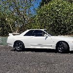
On the blue 2.8 Nitro 32 during a firmware update about six weeks ago I had a slight issue where during the update to my 2500, my coilpacks harness and main engine loom decided to smoke, catch fire and melt. Completely destroyed main harness along firewall and at coilpacks harness power supply plug. Car was running well before this and are using R35 coilpack upgrade from Godzilla motorsport.

Cause was unknown at this stage so ECU was sent back to Haltech for inspection and test, and ends up testing fine. After post mortem on engine loom discovered the earth wire which carries the coilpack power had melted due to excessive current, taking out the rest of the cables it was loomed with. After bringing this up with Haltech the only conclusion I could reach was that during the firmware update it triggered all six coilpacks to try and charge the primary side simultaneously for an extended period of time without discharging, which in turn will make an excessive amount of current flow through the power supply wires to the loom.

If you look at the coilpack 12v supply the positive is also much larger gauge than the ground wire. Compounding this is issue if you run R35 coilpacks which draw considerably more current than stock coils, if this is to happen the risk of cable failure is increased if all coils decide to charge all at once and then not discharge.

After bringing this to Haltechs attention they decided to retain my Elite for further testing, which confirmed that the coilpack outputs could indeed randomly turn on during the firmware update, as the ECU will be in a state of no configuration while erasing the existing firmware and writing the new one.

After receiving back my 2500, on the 21/10/2019 comes a new firmware 2.34.00 which the first changelog mentioned in it was the rectification of the coilpack outputs switching on during a firmware update.

Car was finally finished off yesterday with the original Elite 2500 on 2.34.00, and a whole new wiring specialties main engine and coil pack loom to replace the fried stock one. Fired up first go, no DTC's and all sensors reporting as normal.

Again, Please do update immediately with your coilpacks unplugged


  • Like 5
Link to comment
https://www.sau.com.au/forums/topic/479058-haltech-elite-2500-firmware-23400/
Share on other sites

Ouch. That sort of software "bug" is an absolute bastard to plan for in the hardware and software specification stage and in the programming/testing phase. There are so many possible random such things that could go wrong, it would be hard to imagine them all.

I guess Haltech could take a leaf from the designers of safety critical systems and just make sure that all outputs are off (assumed to be the safe state) at all times when not required - which would be especially true of those edge cases where the ECU program is not actually in charge, ie during flashing. Just needs one or two interlocks to be put in place.

It's surprising that they can fix it just with a firmware update though - so maybe they have already had the physical side of it in place in the original design, older firmwares were doing it properly and somewhere along the way the software side of it got lost or bugged out.

Thank you for that!

Haltech updates sometimes do extremely strange things, not long ago I upgraded the firmware and somehow after the upgrade all my I/O mappings vanished!

Luckily Haltech auto saves maps for you, so imported it back in.

They need to get Andy from Adaptronic (which is pretty much Haltech now) to allow Haltechs to be accessed without the need to be powered up. I remember with the old 440D Adaptronic you could just power it up with a USB and load/mod the map however you wanted it before you even connected it up.

Yeah it would be good to access the ECU while car is off, and ECU was USB powered. The new ESP 2.42 software, which was only released Monday 28/10 also won't upgrade from the old ESP. Have to completely uninstall 2.41 or earlier and fresh install 2.42 ESP. Doesn't erase any saved maps though as they are saved elsewhere.

There is also a bug in the ESP software on the knock control long term trim, which sometimes doesn't apply timing changes permanently to the base ignition map when applied.  Won't melt an engine loom though which was an absolute bastard of a job to replace.

  • Like 1
On 06/11/2019 at 7:50 PM, r32-25t said:

I just did mine, disconnected the igniter and main plug for the coil harness, no issue 

But did you enable rolling anti-lag? Need bang bangs on gear shift 

  • 1 year later...

Ok guys more heads up on Haltech firmware. If you are using 2.38.00 at the moment on an Elite 2500 or 2000 there is a problem with it - get off it now.

The problem is related to running the wideband, causing it to randomly malfunction and get stuck in boot mode. After speaking to Haltech the problem mostly occurs when upgrading to 2.38, but for me this happened when trying to move to 2.39 and the firmware update could not complete. This caused my Elite to lockup and get the wideband stuck in boot mode, which causes the wideband to draw max current.

Basically to fix it I had to go back from 2.38 to 2.37, then move to 2.39.01 which corrected the issue. If you're not on 2.38 don't worry as Haltech have since removed it from the firmware update list and is no longer obtainable.

There is also a new ESP pack 2.47.01 available too, which is not downloadable on their site. It is only installable though your existing ESP software when the ESP is using online connection.

  • Like 1

Create an account or sign in to comment

You need to be a member in order to leave a comment

Create an account

Sign up for a new account in our community. It's easy!

Register a new account

Sign in

Already have an account? Sign in here.

Sign In Now


  • Similar Content

  • Latest Posts

    • Yeah, that's fine**. But the numbers you came up with are just wrong. Try it for yourself. Put in any voltage from the possible range and see what result you get. You get nonsense. ** When I say "fine", I mean, it's still shit. The very simple linear formula (slope & intercept) is shit for a sensor with a non-linear response. This is the curve, from your data above. Look at the CURVE! It's only really linear between about 30 and 90 °C. And if you used only that range to define a curve, it would be great. But you would go more and more wrong as you went to higher temps. And that is why the slope & intercept found when you use 50 and 150 as the end points is so bad halfway between those points. The real curve is a long way below the linear curve which just zips straight between the end points, like this one. You could probably use the same slope and a lower intercept, to move that straight line down, and spread the error out. But you would 5-10°C off in a lot of places. You'd need to say what temperature range you really wanted to be most right - say, 100 to 130, and plop the line closest to teh real curve in that region, which would make it quite wrong down at the lower temperatures. Let me just say that HPTuners are not being realistic in only allowing for a simple linear curve. 
    • I feel I should re-iterate. The above picture is the only option available in the software and the blurb from HP Tuners I quoted earlier is the only way to add data to it and that's the description they offer as to how to figure it out. The only fields available is the blank box after (Input/ ) and the box right before = Output. Those are the only numbers that can be entered.
    • No, your formula is arse backwards. Mine is totally different to yours, and is the one I said was bang on at 50 and 150. I'll put your data into Excel (actually it already is, chart it and fit a linear fit to it, aiming to make it evenly wrong across the whole span. But not now. Other things to do first.
    • God damnit. The only option I actually have in the software is the one that is screenshotted. I am glad that I at least got it right... for those two points. Would it actually change anything if I chose/used 80C and 120C as the two points instead? My brain wants to imagine the formula put into HPtuners would be the same equation, otherwise none of this makes sense to me, unless: 1) The formula you put into VCM Scanner/HPTuners is always linear 2) The two points/input pairs are only arbitrary to choose (as the documentation implies) IF the actual scaling of the sensor is linear. then 3) If the scaling is not linear, the two points you choose matter a great deal, because the formula will draw a line between those two points only.
    • Nah, that is hella wrong. If I do a simple linear between 150°C (0.407v) and 50°C (2.98v) I get the formula Temperature = -38.8651*voltage + 165.8181 It is perfectly correct at 50 and 150, but it is as much as 20° out in the region of 110°C, because the actual data is significantly non-linear there. It is no more than 4° out down at the lowest temperatures, but is is seriously shit almost everywhere. I cannot believe that the instruction is to do a 2 point linear fit. I would say the method I used previously would have to be better.
×
×
  • Create New...