

Announcements
-
Similar Content
-
-
Latest Posts
-
 Hope you aren't too sore after that one, might take a day or 2 to notice yet and I guess it is a loooooong drive home. On the bright side, tube frame front end is a thing at superlap, right?
 -

-
 The chart of front pressure to rear pressure (with one being on the x axis and the other being on the y axis) is not a straight line on a typical proportioning valve. At lower pressures there is a straight line with one slope, and at higher pressures that changes to a lower slope. That creates a bend in the line at that pressure, called the knee point. If you do not change the proportionng as the pressure gets higher, you will suffer excessive pressure (at one end of the car or the other, depending on which way you look at the proportioning action) and then get lockups at that end. The HFM BM57, from my memory of previous discussions, is based on the BM57 from a different car (to a Skyline), with a different requirement for the location of the knee point and the distribution of pressure front to rear, and so is not a good choice for an upgrade on a Skyline. Here's a couple of links to some old posts, one from here, one from elsewhere. A lot of it pertains to adjustable prop valves, but the idea is the same. There are plenty of discussions on here about this issue from al the many years of people wanting a cheap/accessible option. https://grassrootsmotorsports.com/forum/grm/learn-me-brake-proportioning-valves/236880/page1/ https://grassrootsmotorsports.com/forum/grm/learn-me-brake-proportioning-valves/236880/page1/
 -

By No Crust Racing · Posted
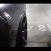
Yeah dunno why johhny posted that here with no context, just post on FB/insta bro where he put it up? Laine had an off at T4 during Thurs prac, he's ok, car is less than perfect, they are done for the weekend, he can fill in the rest. Bando also binned it like 100m up the road. -
 I feel there must have been a FB/insta post and the weekend did not start well at all I hope everyone is all okay
-


Recommended Posts
Create an account or sign in to comment
You need to be a member in order to leave a comment
Create an account
Sign up for a new account in our community. It's easy!
Register a new accountSign in
Already have an account? Sign in here.
Sign In Now