Jump to content
SAU Community

Group Buy : Stealth/Boot wing for R33


Recommended Posts

Hi.

Al (SAU Vic Vice Pres) will be inspecting the quality of the wing from the supplier in melbourne. If all goes well, we will be buying from that guy. I will also get quotes for all of you who are in other states.

Give us a bit more time, I will update this thread soon.

Cheers

  • Replies 127
  • Created
  • Last Reply

Top Posters In This Topic

UPDATE

Al (VIC SAU Vice President) inspected the wing from the supplier (Allblitz) in Melbourne this evening. He is pleased with the quality and fitting, and thus we and a couple more people in Melbourne will be placing orders very soon. We are just waiting for anyone else who wants to join in this group buy.

The price is $200 per wing if we can get 3 or more buyers. I will speak to Allblitz to ask if we can get a better price if there is a big number of interested buyers.

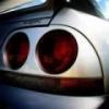
I have also included 4 pictures which Allblitz sent me. Please PM me or Allblitz regarding this group buy. You can PM Allblitz to get shipping quotes if you're not from Melbourne.

I will be posting a list of Confirmed Interested Buyers tomorrow. Please contact me if you're seriously interested so I can add you to that list.

Cheers

As mentioned by ZigenGT, I will be supplying the Stealth wings for $200 (Melbourne and Sydney Only). For those who would want to purchase in other states, I would need to see what costs are to that particular location.

I am going to try and get a further discount from the supplier if I can organise a group buy of 10+ wings.

Regards,

Husnu (Hus).

www.allblitz.com.au

Ok, at the moment I have a price on QLD only.

Cost of Freight to QLD is $16.

Same company does not do WA. So i will have to source some other companies.

Melbourne and Sydney, no extra cost for freight.

Sorry guys, the only place i can organise freight to is Melbourne and Sydney at no extra cost, and Qld C.B.D ($16).

Any other destination, the buyer will have to organise freight. You have the choice of organising freight from Melbourne or Sydney.

Regards,

Husnu.

www.allblitz.com.au

As ZigenGT has mentioned I have personally seen this wing.

At first I was concerned about the fit, as the pictures taken do not have the wing sitting properly. When the wing is flush with the rear end of the boot, the wing fits nicely. The width is just a little short (2 - 3 mm) so the gap between the wing and rear quarters is about 1 - 1.5 mm wider, on each side. When compared to the std wing this is not so bad. I was swapping wings constantly (between std and stealth) and comparing all aspects; how the wing sits, how it lines up along the quarters (from the side, top and rear), etc. By the end of the night I was happy with the quality and fit. If you are concerned about the extra gap it can be compensated for by the panel shop. The wing needs to be fixed to the boot lid with Auto grade glue, as there are no bolts. The wing in the photos has a very slight bow on the L.H.S. This can not be helped as not all moulds, no matter how good they are, come out perfect. This bow was easily corrected with the slightest of pressure on that corner, so when the wing is attached with the glue it will have no trouble sitting flat. I have informed you about all my observations, so that you can all make a clear decision on purchasing this wing. I am confident that these wings are of the same quality that is offered from JMS and Unique Autosports, the only difference is the price. This is probably why the pics on these sites do not show close-ups of the wings on the cars (in regard to the gapping between the wing and the guards).

Hus (Allblitz) has requested a deposit from each supplier be taken b4 the order is put through. I have decided that a non-refundable $50 deposit is adequate and will ensure that potential buyers are serious and will not pull out. Due to my presence on this forum I will be collecting the money on behalf of ZigenGT and Allblitz (Hus), once I have enough buyers I will then give the money and order to Hus. When the wings are made and ready for pick-up the remaining balance can be sorted with Hus (on pick-up from Melb/Syd) or transferred into my account and the goods delivered.

ALL INTERESTED BUYERS PLEASE PM ME AND I WILL PM YOU MY ACCOUNT DETAILS. If you have any questions I will be more than happy to answer them.

Alan

SAU Vic. - Vice President

I personally am going to mount a GT wing in front of this wing. This will neaten up the look of the boot line. I am only going to have the GT wing on for club circuit days and other such activities :P.

Are these the wings people buy to then mount a GT wing to their R33?

As there has been quite a number of inquires for shipping to WA, I will be asking Allblizt to see if he can arrange another shipping company or something. I have personally used Bus Freight before twice and they were very efficient. Perhaps they can be shipped to WA this way, but I have to ask Allblitz first.

Also Al has taken the trouble to view the wing & share his thoughts about the wing here, so please let him know if you're interested in the group buy.

Thanks!

Guest
This topic is now closed to further replies.


  • Similar Content

  • Latest Posts

    • Wheel alignment immediately. Not "when I get around to it". And further to what Duncan said - you cannot just put camber arms on and shorten them. You will introduce bump steer far in excess of what the car had with stock arms. You need adjustable tension arms and they need to be shortened also. The simplest approach is to shorten them the same % as the stock ones. This will not be correct or optimal, but it will be better than any other guess. The correct way to set the lengths of both arms is to use a properly built/set up bump steer gauge and trial and error the adjustments until you hit the camber you need and want and have minimum bump steer in the range of motion that the wheel is expected to travel. And what Duncan said about toe is also very true. And you cannot change the camber arm without also affecting toe. So when you have adjustable arms on the back of a Skyline, the car either needs to go to a talented wheel aligner (not your local tyre shop dropout), or you need to be able to do this stuff yourself at home. Guess which approach I have taken? I have built my own gear for camber, toe and bump steer measurement and I do all this on the flattest bit of concrete I have, with some shims under the tyres on one side to level the car.
    • Thought I would get some advice from others on this situation.    Relevant info: R33 GTS25t Link G4x ECU Walbro 255LPH w/ OEM FP Relay (No relay mod) Scenario: I accidentally messed up my old AVS S5 (rev.1) at the start of the year and the cars been immobilised. Also the siren BBU has completely failed; so I decided to upgrade it.  I got a newer AVS S5 (rev.2?) installed on Friday. The guy removed the old one and its immobilisers. Tried to start it; the car cranks but doesnt start.  The new one was installed and all the alarm functions seem to be working as they should; still wouldn't start Went to bed; got up on Friday morning and decided to have a look into the no start problem. Found the car completely dead.  Charged the battery; plugged it back in and found the brake lights were stuck on.  Unplugging the brake pedal switch the lights turn off. Plug it back in and theyre stuck on again. I tested the switch (continuity test and resistance); all looks good (0-1kohm).  On talking to AVS; found its because of the rubber stopper on the brake pedal; sure enough the middle of it is missing so have ordered a new one. One of those wear items; which was confusing what was going on However when I try unplugging the STOP Light fuses (under the dash and under the hood) the brake light still stays on. Should those fuses not cut the brake light circuit?  I then checked the ECU; FP Speed Error.  Testing the pump again; I can hear the relay clicking every time I switch it to ON. I unplugged the pump and put the multimeter across the plug. No continuity; im seeing 0.6V (ECU signal?) and when it switches the relay I think its like 20mA or 200mA). Not seeing 12.4V / 7-9A. As far as I know; the Fuel Pump was wired through one of the immobiliser relays on the old alarm.  He pulled some thick gauged harness out with the old alarm wiring; which looks to me like it was to bridge connections into the immobilisers? Before it got immobilised it was running just fine.  Im at a loss to why the FP is getting no voltage; I thought maybe the FP was faulty (even though I havent even done 50km on the new pump) but no voltage at the harness plug.  Questions: Could it be he didnt reconnect the fuel pump when testing it after the old alarm removal (before installing the new alarm)?  Is this a case of bridging to the brake lights instead of the fuel pump circuit? It's a bit beyond me as I dont do a lot with electrical; so have tried my best to diagnose what I think seems to make sense.  Seeking advice if theres for sure an issue with the alarm install to get him back here; or if I do infact, need an auto electrician to diagnose it. 
    • Then, shorten them by 1cm, drop the car back down and have a visual look (or even better, use a spirit level across the wheel to see if you have less camber than before. You still want something like 1.5 for road use. Alternatively, if you have adjustable rear ride height (I assume you do if you have extreme camber wear), raise the suspension back to standard height until you can get it all aligned properly. Finally, keep in mind that wear on the inside of the tyre can be for incorrect toe, not just camber
    • I know I have to get a wheel alignment but until then I just need to bring the rear tyres in a bit they're wearing to the belt on the inside and brand new on the outside edge. I did shorten the arms a bit but got it wrong now after a few klms the Slip and VDC lights come on. I'd just like to get it to a point where I can drive for another week or two before getting an alignment. I've had to pay a lot of other stuff recently so doing it myself is my only option 
    • You just need a wheel alignment after, so just set them to the same as current and drive to the shop. As there are 2 upper links it may also be worth adding adjustable upper front links at the same time; these reduce bump steer when you move the camber (note that setting those correctly takes a lot longer as you have to recheck the camber at each length of the toe arm, through a range of movement, so you could just ignore that unless the handling becomes unpredictable)
×
×
  • Create New...