
Summary: Front Mount Intercooler Options & Piping Layouts

Announcements
-
Similar Content
-
-
Latest Posts
-
 Biggest thing is you're okay! It sounds like between the accident, and the drive home, it was a pretty torturous trip again! On the bright side, you took the opportunity to enjoy the event more from the perspective of a spectator, than as an entrant! Sad to see so much damage to the car. It really has taken a HUGE hit in the front end. If/when you choose to repair, hopefully the rails are straight (At least from shock tower backwards). Hopefully the extra cage coming through there has save most of the chassis rails, and HOPEFULLY saved the motor too. Best of luck when you eventually get motivated to start pulling it down to check it all out
 -
Sounds more like what Brad said, that it's mainly transfer. What pad bed in procedure did you use, and did you replace/machine the rotors, or just swap pads?
-
 The stutter is almost entirely in the pedal. I don't feel the brakes release and reapply as you would with ABS engaging but the pedal feels that way, without the brakes releasing. It only lasts for less than a second and the pedal is fine again. It's hard to explain, sorry. I'll get under this weekend and just double check everything is tight. Fluid is at max where I left it.
 -
What bedding in procedure did you use? When you say stutter, what exactly do you mean? Like it feels like someone letting go of the brakes momentarily and regrabbing them again to get you to stop? Re-reading your post, and that is what it kind of makes me think you're explaining, like theres a little bit of a jolt, likely just as you're reaching a stop. I've only had this issue once. And if its caused by what caused mine, you will want to get the car up on stands again and check it over. Mine was a case of a caliper mounting bolt coming out and letting the caliper rotate on the other remaining bolt and gave play in a wheel as it came to a stop. But not every stop either!
-
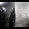
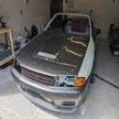
 Yeop... binned it This will be a summary will not many pics atm and cbf Fixed the samsonas - it was totally munched Put a new precision 7675 T4 on with proper split pulse mani Got to Sydney to get to car - drove to canberra to get racecar - drive back to sydney that night Next day all day at Plasmaman putting on new clamps cleaning some things up and adding another large engine oil cooler sitting at the rear above diffuser to keep things cooler Next day - Tuesday - on Dyno - killer wikid awesome pumped out really good numbers - more mid range and on lower boost levels Wednesday - first prac - all day again getting the suspension right - had to borrow front suspension again - out do a lap come in - out do a lap - in - what i had just couldnt handle the load at the more consistent higher speeds - got a lap in at the end of the day that was pretty reasonable Put it this way that lap wouldve had me in 4th in Pro am for the whole event - with only 700 hp and used tyres Thurs first official prac day - lap out warm up - then entered a hotlap with above setting and 80% effort took corners 1,2,3 and into 4 car felt awesome - rear came around out of nowhere bang into the wall near front on at whatever 140 kmph Done, over, gone Just one of those how did that happen apparently as all indications show nothing out of the ordinary Got to spend the rest of the time at the event like I hadnt done before - was actually Ok mainly as I had my family and my boy is 9 and got treated like a rockstar Long trip home, lost a trailer wheel in nowhere land, X5 airbag suspension gave up half way across nullabour and rode on bumps stops (its now completely fine) had to do a 19 hr drive day on day 3 as accommodation got screwed up so just had to keep driving till found a town with some Now to reassess - hopefully the motor and other things are OK but yet to be seen too. There is no easy fix there is no i'll just order that part and get it sent - we'll have a talk to people see what can happen and what the go is but at minimum its rebuild from scratch struts forward and alot of time effort and $ should and if I return and if but maybe/ when I have the cage tied into the front strut towers - if I didnt have that things couldnt been worse you can say its just a front end but if you know what goes into these cars... you'll know what that actually means in reality Car was very fast. Disappointing we just didnt get to show it Effort doesnt win you races though Apparently this is motorsport !
-


Recommended Posts
Create an account or sign in to comment
You need to be a member in order to leave a comment
Create an account
Sign up for a new account in our community. It's easy!
Register a new accountSign in
Already have an account? Sign in here.
Sign In Now