

Announcements
-
Similar Content
-
-
Latest Posts
-
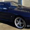
 😬 This is still for sale. And it's had zero price updates. https://www.carsales.com.au/cars/details/2002-holden-commodore-s-vx-ii-manual/SSE-AD-12765398
 -
 The AR-X Four is a "crossover" type model with enhanced offroad ability over the normal models. I'd be basing my decision on that to be honest. The AR-X has slightly worse fuel consumption as it's about 40kg heavier, and has a bit higher ground clearance.
 -
 Yep, I agree. I can't stand modern cars and their dashes that are all screens and you can't dim the bastards dark enough! I'm constantly being blinded in a modern car!
 -
Yep. I love the inside of my E39. Not sporty by any stretch but the epitome of "only what you need".
-
 Buy whichever one makes you happiest when you sit in it. After all, that's where you'll be experiencing it.
-


Recommended Posts
Create an account or sign in to comment
You need to be a member in order to leave a comment
Create an account
Sign up for a new account in our community. It's easy!
Register a new accountSign in
Already have an account? Sign in here.
Sign In Now