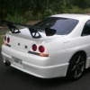
Jump to content
SAU Community

Recommended Posts

Not sure if this has been mentioned...

I recently got my RB25/30 running (last Tuesday). I did the mod for the VCT, however, all I did was grub screw the hole in the head, with no other modification. My VCT works perfect. No oil control/lack of oil issues or anything (this was mod was done on the advice of my engine builder).

Discuss.

u mean to say u didnt do either internal(from buckets) or external oil feed to the VCT solenoid and it still works??

u mean to say u didnt do either internal(from buckets) or external oil feed to the VCT solenoid and it still works??

Correct. All I did was the grub screw mod to stop oil/water mixing. Bolted the head on (of course all of this on the advice of engine builder) and it works fine. This has been done on my mates twin came RB30 and his also works.

quick question guys, got a 6boost high mount mani and a gt35r turbo,did anyone have to re -postion any of the front or rear housings on the turbo to position the turbo correctly on the mani.my mani is a t3 flange,fits perfetly,so no problem there!

yes you will need to losen the front housing so you can align it properly with where you want it.

make sure the oil feed into the turbo is facing straight up

thought so cheers!i wont be doing it,just a stupid ? really, but there is no stupid ? on here!

ive just gotten hold of a NA rb30 bottom end and gonna to the usual build, ie rods pistons and so on, just wonder a few things...

1. is there any difference with the rb30 NA and Turbo Crank

2. can the rb30 crank be fitted to a rb25 block to get around drilling and taping holes in the rb30 block, read somewhere that this was possible and if not what is the best way about doing the tensioner for the belt if the pre tapped hole is not there.

3. is there any other differences between the turbo and NA rb30 block itself.

Using a 25 head, cheers for any help :)

Edited by fomby639
ive just gotten hold of a NA rb30 bottom end and gonna to the usual build, ie rods pistons and so on, just wonder a few things...

1. is there any difference with the rb30 NA and Turbo Crank

no

2. can the rb30 crank be fitted to a rb25 block to get around drilling and taping holes in the rb30 block, read somewhere that this was possible and if not what is the best way about doing the tensioner for the belt if the pre tapped hole is not there.

no

3. is there any other differences between the turbo and NA rb30 block itself.

no, but there is a small difference between S1 and S2 blocks in relation to the flat area where the tensioner goes, the S2 block is a little easier.

Using a 25 head, cheers for any help ;)

Cheers

Gary

Some of the S1 blocks don't have the turbo oil feed drilled all the way through, check it with a piece of wire and make sure it goes all the way through the block and into the gallery behind the oil filter housing. You can drill it, just need a long series drill to do it. I've only seen one block like that but it's worth a check.

  • 2 weeks later...

hey guys! Sorry its been a while have been so caught up with work and studies haven't really had much time to spend online or on cars sadly :banana: But i have managed to FINALLY get mine trouble free and tuned. How is all the rb30's out there? Hope all is going well for the festive season.

On a quick note has anyone has issues with the speedometer drive/cable on the bigger rb25det gearbox? For some reason my gearbox keeps shredding the plastic part at the end of the drive, It was all fine until i took it out onto the open road sitting around 100km this is the second time its happened and was wondering if someone knew a way around it?

do most of you guys get more area welded onto the head on the front water gallery i think it is how its different from the rb30 block? i got my head rebuilt but didnt know about getting that bit modded to get more gasket sealing area there. will it be ok to leave it how it is?

its a rb25det head from a r33

Edited by joe blo
How closely are you following the writeups for the speedo sender? are you cutting a new groove and rotating the sender 180'?

too be honest i didnt know there was one lol. Um i was thinking maybe it was because of the bigger motor it was doing this? I have yet to pull the speedo drive out a second time to confirm that it has chewed the plast gears, cutting groove and rotating???? I'm not aware of this

too be honest i didnt know there was one lol. Um i was thinking maybe it was because of the bigger motor it was doing this? I have yet to pull the speedo drive out a second time to confirm that it has chewed the plast gears, cutting groove and rotating???? I'm not aware of this

Read the writeups!!

You basically need to rotate the sender 180 deg otherwise the gear mesh is too great and it chews the gears out.

  • 3 weeks later...

hey people, great thread this one has been a great read!!!!

i am just about to do the following

put series 2 stock rb30 bottom end, with new bearings and piston rings

onto a stock series rb25 head.

how much should i be charged for this in labour? i have benn qouted $2500 nearly $3000

bear in mind this is to keep vvt also

any help and advice on whethter this labour price is good please let me know, i think its way too much

Guys I was just doing some casual reading AGAIN on the RB30DOHC guide, and in relation tot heR33 RB25 head, it claims you will need to:

"The R33 RB25 also requires you to plumb in an external head oil return, you can T in to the turbo drain."

What is the external head oil return it speaks of? Is this the standard one at the front of the head that needs to be T'd in?

I'm on my second RB30DOHC motor, and never had this fitted... What issues are normally seen if this isn't plumbed in?

Create an account or sign in to comment

You need to be a member in order to leave a comment

Create an account

Sign up for a new account in our community. It's easy!

Register a new account

Sign in

Already have an account? Sign in here.

Sign In Now


  • Similar Content

  • Latest Posts

    • No, your formula is arse backwards. Mine is totally different to yours, and is the one I said was bang on at 50 and 150. I'll put your data into Excel (actually it already is, chart it and fit a linear fit to it, aiming to make it evenly wrong across the whole span. But not now. Other things to do first.
    • God damnit. The only option I actually have in the software is the one that is screenshotted. I am glad that I at least got it right... for those two points. Would it actually change anything if I chose/used 80C and 120C as the two points instead? My brain wants to imagine the formula put into HPtuners would be the same equation, otherwise none of this makes sense to me, unless: 1) The formula you put into VCM Scanner/HPTuners is always linear 2) The two points/input pairs are only arbitrary to choose (as the documentation implies) IF the actual scaling of the sensor is linear. then 3) If the scaling is not linear, the two points you choose matter a great deal, because the formula will draw a line between those two points only.
    • Nah, that is hella wrong. If I do a simple linear between 150°C (0.407v) and 50°C (2.98v) I get the formula Temperature = -38.8651*voltage + 165.8181 It is perfectly correct at 50 and 150, but it is as much as 20° out in the region of 110°C, because the actual data is significantly non-linear there. It is no more than 4° out down at the lowest temperatures, but is is seriously shit almost everywhere. I cannot believe that the instruction is to do a 2 point linear fit. I would say the method I used previously would have to be better.
    • When I said "wiring diagram", I meant the car's wiring diagram. You need to understand how and when 12V appears on certain wires/terminals, when 0V is allowed to appear on certain wires/terminals (which is the difference between supply side switching, and earth side switching), for the way that the car is supposed to work without the immobiliser. Then you start looking for those voltages in the appropriate places at the appropriate times (ie, relay terminals, ECU terminals, fuel pump terminals, at different ignition switch positions, and at times such as "immediately after switching to ON" and "say, 5-10s after switching to ON". You will find that you are not getting what you need when and where you need it, and because you understand what you need and when, from working through the wiring diagram, you can then likely work out why you're not getting it. And that will lead you to the mess that has been made of the associated wires around the immobiliser. But seriously, there is no way that we will be able to find or lead you to the fault from here. You will have to do it at the car, because it will be something f**ked up, and there are a near infinite number of ways for it to be f**ked up. The wiring diagram will give you wire colours and pin numbers and so you can do continuity testing and voltage/time probing and start to work out what is right and what is wrong. I can only close my eyes and imagine a rat's nest of wiring under the dash. You can actually see and touch it.
×
×
  • Create New...