justified2.4 Posted October 5, 2003 Share Posted October 5, 2003 "Holy intake manifold, Batman!" Very nice intake manifold plenum, who made that one for you? Link to comment https://www.sau.com.au/forums/topic/26011-putting-an-extra-turbo-to-the-r33-gtst/page/2/#findComment-556899 Share on other sites More sharing options...
blind_elk Posted October 5, 2003 Share Posted October 5, 2003 Originally posted by JimX Two stock turbos will be able to be provide more boost to one engine because they're only feeding half the engine.... But they are feeding a common plenum chamber. The laws of physics dictate that the pressure will be distributed evenly throughout the induction system. Therefore you can only run boost equivalent to the lesser of the 2 turbos. So if you're running 9psi on each turbo, you can only run 9psi at the wastegates, and therefore 9psi at the valves. If you are running 18psi on each (ceramic) turbo, you are flirting with danger. Link to comment https://www.sau.com.au/forums/topic/26011-putting-an-extra-turbo-to-the-r33-gtst/page/2/#findComment-556955 Share on other sites More sharing options...
B-Man Posted October 5, 2003 Share Posted October 5, 2003 Maybe more 'flow' at same boost ???? Link to comment https://www.sau.com.au/forums/topic/26011-putting-an-extra-turbo-to-the-r33-gtst/page/2/#findComment-556956 Share on other sites More sharing options...
rbs13 Posted October 6, 2003 Share Posted October 6, 2003 i thought japanese motor sport were in adelaide? and i thought a guy from melbourne made the plenum? Link to comment https://www.sau.com.au/forums/topic/26011-putting-an-extra-turbo-to-the-r33-gtst/page/2/#findComment-557085 Share on other sites More sharing options...
Sydneykid Posted October 6, 2003 Share Posted October 6, 2003 Hi stimps, "You can run 18psi with one of these turbos" We ran 12 psi on an low K's R34 RB25DET turbo for 8 minutes and it did the usual ceramic turbine thing. I have 10 other examples on various RB20/25's, you are the exception not the rule. "by having the right intercooler and tuning" Firstly it is the combination of heat and resistance that causes the ceramic turbine to fail, not just resistance. Is is simple physics, turn the boost up and you have to retard the ignition timing otherwise it pings. When you retard the ignition timing, the spark fires later in the combustion stroke. Therefore combustion takes place later, such that at higher rpm the exhaust valve opens before the combustion is all finished and some actually takes place in the exhaust manifold and turbo. Bingo extra heat on the ceramic turbine. The more boost, the more retarded the ignition, the more combustion in the turbo, the more heat. Add that to a few hard laps of the circuit or a long hard run on the freeway or drag strip and you will be picking turbine bits out of the cat. Anyway, that's been my experience and 10 others I have fixed. Roll the dice if you like. Link to comment https://www.sau.com.au/forums/topic/26011-putting-an-extra-turbo-to-the-r33-gtst/page/2/#findComment-557200 Share on other sites More sharing options...
Sydneykid Posted October 6, 2003 Share Posted October 6, 2003 While I'm at it, "478kw at the wheels with a stock bottom end R33" I could make a 1,000 bhp out of a standard RB25DET bottom end, on Elf Turbomax, shoot that's easy. But for how long, 22 seconds while I do 1 Shootout mode power run on the dyno? Me, I like to drive my car at full power every day, whenever I like, rain, hail or shine, on the track, road or circuit. Fill it up at the local BP and I'm away. Hope that explains my thoughts. Link to comment https://www.sau.com.au/forums/topic/26011-putting-an-extra-turbo-to-the-r33-gtst/page/2/#findComment-557213 Share on other sites More sharing options...
Sydneykid Posted October 6, 2003 Share Posted October 6, 2003 Hi stimps.... "is that with a stock cooler? " no, HKS in a couple, GTR in a couple more, GReddy in 3, and a couple of locals - Micks Metalcraft and Performance Metalcraft. No Standards. The JMS 478KW car.. Is that the one that boiled its brains out recently at Gawler?? I understand it blew the head gasket and split the cylinder head... and when they pulled the head of it had severe detonation on the piston crowns, and suspected broken ringlands. Or maybe that was another of their cars they pushed beyond the limit....... The problem is heat in the exhaust, not heat in the inlet. The intercooler is irrellevant in this scenario. More boost at the engine = more retarded ignition = more heat in the exhaust. Remember, it is not how hard you push it, but how long you push it. Link to comment https://www.sau.com.au/forums/topic/26011-putting-an-extra-turbo-to-the-r33-gtst/page/2/#findComment-557996 Share on other sites More sharing options...
Ronin 09 Posted October 6, 2003 Share Posted October 6, 2003 Hey Sydneykid, don't want to start a "dynos runs and rwkW don't mean a thing, dynos are only good for tuning" argument, but just curious what the RB31det in your R32 makes? No other motives, just plain curious what a long stroke monster will make Link to comment https://www.sau.com.au/forums/topic/26011-putting-an-extra-turbo-to-the-r33-gtst/page/2/#findComment-558005 Share on other sites More sharing options...
Cubes Posted October 6, 2003 Share Posted October 6, 2003 The JMS R33 was running around the 350rwkw mark at the Drift Day. I wondered if the motor had died as on its last couple of laps due to it bouncing off the rev limiter constantly I saw smoke emitting from the exhaust. My Small RB20 turbo has been pretty good to me running 16psi since I got the FMIC around 1.5yrs ago. Its not so much how much a long stroke motor will make its about where it makes it. After looking at my RB30 block compared to a 250 Ford 6 motor the RB30 looks very small. Link to comment https://www.sau.com.au/forums/topic/26011-putting-an-extra-turbo-to-the-r33-gtst/page/2/#findComment-558022 Share on other sites More sharing options...
Sydneykid Posted October 6, 2003 Share Posted October 6, 2003 Hey Ronin09. There are 5 RB31's in the current batch. For curcuit racing, we have found anything more than 650BHP is actually slower, so we will be limiting the curuit engine to a very responsive 625BHP. One of them is going in a drag car, with twin 3037's, so it shgould comfortably make more than 1000BHP. So it is really a matter of what you hang off the engine, as the internals have quite a large spread of horsepower potential. Hope that answers the question. Link to comment https://www.sau.com.au/forums/topic/26011-putting-an-extra-turbo-to-the-r33-gtst/page/2/#findComment-558026 Share on other sites More sharing options...
mambastu Posted October 6, 2003 Share Posted October 6, 2003 Stimps, are those two standard RB25DET turbos ? Link to comment https://www.sau.com.au/forums/topic/26011-putting-an-extra-turbo-to-the-r33-gtst/page/2/#findComment-558254 Share on other sites More sharing options...
stimps Posted October 6, 2003 Share Posted October 6, 2003 yup Link to comment https://www.sau.com.au/forums/topic/26011-putting-an-extra-turbo-to-the-r33-gtst/page/2/#findComment-558328 Share on other sites More sharing options...
Steve Posted October 7, 2003 Share Posted October 7, 2003 Sydneykid, where did you hear about JMS's R33? Usually that sort of news spreads pretty quickly in SA, but I havent heard a thing yet. Link to comment https://www.sau.com.au/forums/topic/26011-putting-an-extra-turbo-to-the-r33-gtst/page/2/#findComment-558337 Share on other sites More sharing options...
Steve Posted October 7, 2003 Share Posted October 7, 2003 Stimps, where abouts it the JMS shop in sydney? do they have a web site up? Link to comment https://www.sau.com.au/forums/topic/26011-putting-an-extra-turbo-to-the-r33-gtst/page/2/#findComment-558339 Share on other sites More sharing options...
Sydneykid Posted October 7, 2003 Share Posted October 7, 2003 Hmmmmm, we buy lots from JMS, it always comes up from Adelaide. Link to comment https://www.sau.com.au/forums/topic/26011-putting-an-extra-turbo-to-the-r33-gtst/page/2/#findComment-558740 Share on other sites More sharing options...
Steve Posted October 7, 2003 Share Posted October 7, 2003 Originally posted by stimps oh, and japanese motorsport in sydney got 478kw at the wheels with a stock bottom end R33 so use that as a bit of benchmark when it comes to how strong the motor is. (in other words, bloody strong) Just thought I would give JMS a call - they do not have a shop in sydney. I would appear stimps you are either very confused or full of shit. Either way I think it is a good idea to get stuff right before you start to post up making claims. There is enough dis-information around already, adding to it doesnt help. A warning to others that may listen too long or hard to your comments. Link to comment https://www.sau.com.au/forums/topic/26011-putting-an-extra-turbo-to-the-r33-gtst/page/2/#findComment-558844 Share on other sites More sharing options...
Steve Posted October 7, 2003 Share Posted October 7, 2003 they must of shipped it to adelaide???? the car was built in adelaide, and resides in adeliade as does the owner, Danny Vahoumis, who is also the proprietor of JMS. The car travelled to sydney once, but that is a completely different story. Also the car made 448rwkw, not 478rwkw. You really should get things straight before you sprout them as truth - otherwise, as stated before, all you do is add to confusion and the already huge amount of disinformation on the net which helps no one. Plus you have just shot your credibility to pieces on here. Link to comment https://www.sau.com.au/forums/topic/26011-putting-an-extra-turbo-to-the-r33-gtst/page/2/#findComment-559844 Share on other sites More sharing options...
supra Posted October 15, 2003 Author Share Posted October 15, 2003 bump Link to comment https://www.sau.com.au/forums/topic/26011-putting-an-extra-turbo-to-the-r33-gtst/page/2/#findComment-570394 Share on other sites More sharing options...
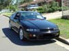
neil_se Posted October 20, 2003 Share Posted October 20, 2003 here's a pic of a tt rb25. it uses twin hks2530s and makes about 400rwkw. its in an s13 silvia daily driver and has run 10.8. Link to comment https://www.sau.com.au/forums/topic/26011-putting-an-extra-turbo-to-the-r33-gtst/page/2/#findComment-575311 Share on other sites More sharing options...
stimps Posted October 26, 2003 Share Posted October 26, 2003 Thats nice. Me likes. Link to comment https://www.sau.com.au/forums/topic/26011-putting-an-extra-turbo-to-the-r33-gtst/page/2/#findComment-581773 Share on other sites More sharing options...


Recommended Posts
Create an account or sign in to comment
You need to be a member in order to leave a comment
Create an account
Sign up for a new account in our community. It's easy!
Register a new accountSign in
Already have an account? Sign in here.
Sign In Now