
What Have You Done To Your Stagea Lately?

Announcements
-
Similar Content
-
-
Latest Posts
-
 Well, that's kinda the point. The calipers might interfere with the inside of the barrels 16" rims are only about 14" inside the barrels, which is ~350mm, and 334mm rotors only leave about 8mm outboard for the caliper before you get to 350, And.... that;s not gunna be enough. If the rims have a larger ID than that, you might sneak it in. I'd be putting a measuring stick inside the wheel and eyeballing the extra required for the caliper outboard of the rotor before committing to bolting it all on.
 -
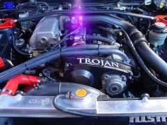
 OK, so again it has been a bit of a break but it was around researching what had been done since I didn't have access to Neil's records and not everything is obvious without pulling stuff apart. Happily the guy who assembled the engine had kept reasonable records, so we now know the final spec is: Bottom end: Standard block and crank Ross 86.5mm forgies, 9:1 compression Spool forged rods Standard main bolts Oil pump Spool billet gears in standard housing Aeroflow extended and baffled sump Head Freshly rebuilt standard head with new 80lb valve springs Mild porting/port match Head oil feed restrictor VCT disabled Tighe 805C reground cams (255 duration, 8.93 lift) Adjustable cam gears on inlet/exhaust Standard head bolts, gasket not confirmed but assumed MLS External 555cc Nismo injectors Z32 AFM Bosch 023 Intank fuel pump Garret 2871 (factory housings and manifold) Hypertune FFP plenum with standard throttle Time to book in a trip to Unigroup
 -

-
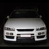
Well, apparently they do fit, however this wont be a problem if not because the car will be stationary while i do the suspension work. I was just going to use the 16's to roll the old girl around if I needed to. I just need to get the E90 back on the road first. Yes! I'm a believer! 🙌 So, I contacted them because the site kinda sucks and I was really confused about what I'd need. They put together a package for me and because I was spraying all the seat surfaces and not doing spot fixes I decided not to send them a headrest to colour match, I just used their colour on file (and it was spot on). I got some heavy duty cleaner, 1L of colour, a small bottle of dye hardener and a small bottle of the dye top coat. I also got a spray gun as I needed a larger nozzle than the gun I had and it was only $40 extra. From memory the total was ~$450 ish. Its not cheap but the result is awesome. They did add repair bits and pieces to the quote originally and the cost came down significantly when I said I didn't need any repair products. I did it over a weekend. The only issues I had were my own; I forgot to mix the hardener into the dye two coats but I had enough dye for 2 more coats with the hardener. I also just used up all the dye because why not and i rushed the last coat which gave me some runs. Thankfully the runs are under the headrests. The gun pattern wasn't great, very round and would have been better if it was a line. It made it a little tricky to get consistent coverage and I think having done the extra coats probably helped conceal any coverage issues. I contacted them again a few months later so I could get our X5 done (who the f**k thought white leather was a good idea for a family car?!) and they said they had some training to do in Sydney and I could get a reduced rate on the leather fix in the X5 if I let them demo their product on our car. So I agreed. When I took Bec in the E39 to pick it up, I showed them the job I'd done in my car and they were all (students included) really impressed. Note that they said the runs I created could be fixed easily at the time with a brush or an air compressor gun. So, now with the two cars done I can absolutely recommend Colourlock. I'll take pics of both interiors and create a new thread.
-
Power is fed to the ECU when the ignition switch is switched to IGN, at terminal 58. That same wire also connects to the ECCS relay to provide both the coil power and the contact side. When the ECU sees power at 58 it switches 16 to earth, which pulls the ECCS relay on, which feeds main power into the ECU and also to a bunch of other things. None of this is directly involved in the fuel pump - it just has to happen first. The ECU will pull terminal 18 to earth when it wants the fuel pump to run. This allows the fuel pump relay to pull in, which switches power on into the rest of the fuel pump control equipment. The fuel pump control regulator is controlled from terminal 104 on the ECU and is switched high or low depending on whether the ECU thinks the pump needs to run high or low. (I don't know which way around that is, and it really doesn't matter right now). The fuel pump control reg is really just a resistor that controls how the power through the pump goes to earth. Either straight to earth, or via the resistor. This part doesn't matter much to us today. The power to the fuel pump relay comes from one of the switched wires from the IGN switch and fusebox that is not shown off to the left of this page. That power runs the fuel pump relay coil and a number of other engine peripherals. Those peripherals don't really matter. All that matters is that there should be power available at the relay when the key is in the right position. At least - I think it's switched. If it's not switched, then power will be there all the time. Either way, if you don't have power there when you need it (ie, key on) then it won't work. The input-output switching side of the relay gains its power from a line similar (but not the same as) the one that feeds the ECU. SO I presume that is switched. Again, if there is not power there when you need it, then you have to look upstream. And... the upshot of all that? There is no "ground" at the fuel pump relay. Where you say: and say that pin 1 Black/Pink is ground, that is not true. The ECU trigger is AF73, is black/pink, and is the "ground". When the ECU says it is. The Blue/White wire is the "constant" 12V to power the relay's coil. And when I say "constant", I mean it may well only be on when the key is on. As I said above. So, when the ECU says not to be running the pump (which is any time after about 3s of switching on, with no crank signal or engine speed yet), then you should see 12V at both 1 and 2. Because the 12V will be all the way up to the ECU terminal 18, waiting to be switched to ground. When the ECU switches the fuel pump on, then AF73 should go to ~0V, having been switched to ground and the voltage drop now occurring over the relay coil. 3 & 5 are easy. 5 is the other "constant" 12V, that may or may not be constant but will very much want to be there when the key is on. Same as above. 3 goes to the pump. There should never be 12V visible at 3 unless the relay is pulled in. As to where the immobiliser might have been spliced into all this.... It will either have to be on wire AF70 or AF71, whichever is most accessible near the alarm. Given that all those wires run from the engine bay fusebox or the ECU, via the driver's area to the rear of the car, it could really be either. AF70 will be the same colour from the appropriate fuse all the way to the pump. If it has been cut and is dangling, you should be able to see that in that area somewhere. Same with AF71. You really should be able to force the pump to run. Just jump 12V onto AF72 and it should go. That will prove that the pump itself is willing to go along with you when you sort out the upstream. You really should be able to force the fuel pump relay on. Just short AF73 to earth when the key is on. If the pump runs, then the relay is fine, and all the power up to both inputs on the relay is fine. If it doesn't run (and given that you checked the relay itself actually works) then one or both of AF70 and AF71 are not bringing power to the game.
-


Recommended Posts
Create an account or sign in to comment
You need to be a member in order to leave a comment
Create an account
Sign up for a new account in our community. It's easy!
Register a new accountSign in
Already have an account? Sign in here.
Sign In Now