Jump to content
SAU Community

Recommended Posts

MORE SOUTH CIRCUIT ACTION - VIEW ON THE BLOG

The ARDC announced a week prior to the last South circuit event, that the competition was cancelled and will resume to be a practice day. Our original plan was to go to the Wakefield Matsuri which is coming up in a few days, but we figured we’d hit up SC once again.

Kinetic Imagery was out and about again and managed to get a Vid of Benny and I in tandem, its bloody crazy how small his R33 looks next to the Stagea.

420734_632349193447282_1533461725_n.jpg

Eiji from Team Redstage made the trek from the ACT to check out the South circuit, he got plenty of coverage of the Stagea too.

485582_632348416780693_68539144_n.jpg

Benny was killing it, laying down solid runs consistently. Starting to get ballsy on the first corner too … he managed to tap the barrier with his rear bumper, which resulted in it flying away haha.

603420_632349236780611_330970366_n.jpg

I wish I could say the same thing about myself. I was pretty sketchy most of the day and finally started getting some good runs down towards the end of the event. I need to work on my entry to the first corner a lot more too.

524768_632348476780687_959326052_n.jpg

It took me a while, but I managed to convince Julie to bring the S14 out and try the South circuit. She was a little bummed that we are no longer going to Wakefield, but luckily she enjoyed herself and considering it’s her first time out, she destroyed it!

37021_515525301840515_1426531001_n.jpg

I would have thought the Stagea would behave and let me just focus on drifting, but it wasn’t ment to be. In the morning it started popping out the dip stick, something it’s never done before.

249132_632348590114009_461357128_n.jpg

Puzzled to say the least, I gave Anth a call and he told me to vent the catch can. After I did this all was well until I had a glimpse of the oil pressure gauge coming up to the first corner.

It was dropping from 80PSI down to 20-30PSI on full boost. I babied it for a few laps just to see exactly what was going down. It was dropping consistently and only near full boost. So I kept going and hoped for the best.

936708_632348673447334_1467450008_n.jpg

The Stagea survived the day and is running like a champ. When I got home I had a look at my previous videos from the South circuit and it was dropping pressure too.

It seems some GTR owners have had the same problem, and their remedy was to over fill the oil by roughly 1 litre. I used to do this but I think I stopped after the oil cooler install. Hopefully that’ll fix it.

941593_632348940113974_1696912220_n.jpg

I’d love to get my R33 front suspension together before the next day, or even just a wheel alignment and straight tie rods. I’ve been driving with bent rods for 3 maybe 4 events now. I’ve finally figured out why they bend too, which I shall touch on soon.

Thanks to the photographers for the coverage!

Rocking roof racks - view on the blog

thule-roof-rack-stagea.jpg

I’ve had a few Stagea owners ask me about my Thule roof racks, and although I’ve been meaning to do a post about them it’s always slipped my mind when its crunch time. I originally bought these for the Raleigh Raceway matsuri trip late last year. As I needed some way of carrying my spare wheels/tyres up.

I didn’t go to that event in my Stagea, but we chucked them on Benny’s series 2 and definitely came in handy. Anyway my main reason for these was to be able to carry tyres on the roof, and other stuff if I needed to. Benny and I headed down to a place called Roof Rack World in Artarmon. They measured everything up and fitted the Thule gear onto the Stagea. It was all in stock except the fairing, but they went to their supplier and nabbed one. Service was excellent so I’d defiantly check them out if you’re in the market for some.

On-the-road.jpg

So now for what everyone has been waiting for … the part numbers!

•Front spoiler (Fairing) LC871XT
•Rail mount foot pack RT757
•Aero bar pack 120cm GL861

If I recall, I am pretty sure the footpack and bar lengths are similar if not the same to the Toyota RAV4.

There they are finally, sorry for holding out for so long. I had to go through all my paper work and find the part numbers haha.

THE QUEST FOR MORE - PART II - VIEW ON THE BLOG

link-arm-raise-point.jpg

I’m back tracking a bit here but here goes. My modified arms had returned from JDI Fabrication in Melbourne. I was eager as hell to see how they turned out, so as soon as they arrived I dropped everything to open the boxes up. Everything just ozzed quality, the cuts, the welds … I’m super happy with the outcome.

Lets have a look at everything shall we?

modified-knuckle.jpg

First up is JDI’s R33 Skyline knuckle, which happens to be the same that Benny is now running. With most cut and shuts the tie rod point is cut down, and shortened at a slightly different position. This is generally to reduce Ackerman. This means more lock, with less turns of the steering wheel, and the trailering wheel to be similar with the leading wheel.

braced-R33-knuckle.jpg

The knuckles have been braced to ensure strength too.

modified-link-arm.jpg

The bearing carrier on the link arm was raised 30mm, and heavily braced as per my request. These measurements have worked out perfect.

boxed-LCA.jpg

The LCA is a nice piece of work. With a metric threaded rose joint, capable of extending up to 40mm. The boxed underside for strength, and the bump stop was removed for more lock gain. Jamie also made me LCA adaptor mounts to suit free of charge. Talk about service!

R33-knuckle-mock-up.jpg

With the Stagea half apart, I did a rough mock-up to see if my theory’s would be successful. As is they could be a good option if my car was higher, but right now more work is needed.

LCA-contact-with-chassis.jpg

The LCA makes contact with the chassis for a start. I now see why the GTR LCA has many bends and is designed the way it is … Nissan didn’t allow for much clearance with the 4WD subframe.

LCA-revision-diagram.jpg

One of two solutions is to cut down the kink from the LCA so it is flat with the rest of the design. This would allow roughly 15-20mm more clearance. Another way to add more clearance would be to mount the rose joint on a slight angle.

LCA-revision-2-diagram.jpg

The second solution was converting the LCA ball joint, to a rose joint setup with an added spacer to push the LCA down to a more acceptable angle.

castor-rod-extension.jpg

The castor rod lines up to the R33 LCA, but needs to be extended roughly 40mm.

Tie-rod-setup.jpg

Finally the subframe doesn’t offer much room for the rack end. I’ve now figured out why I keep bending them! So I’ll probably end up cutting/bracing a section for the rack end to clear. Though in the above photo it appears that with the tie rod end being spaced down, it may avoid hitting the subframe.

brake-line-clearance.jpg

This is something I’m glad I noticed now. Once I finally get all my gear in, I’ll need a 90 degree bend with a banjo bolt on my brake line to offer clearance, otherwise shit could get messy stat! Cutting part of the sway bar mount is an option, but I don’t think it’ll be a good idea due to the design of it. Though I could get another piece made or brace it.

So is the R33 front conversion do-able? Yes it is, all that’s really needed is the castor rod to be extended and the LCA re-modified. If I went the Ikeya Formula style LCA that could do the job too and would probably be a better option.

However, I have abandoned going down this path. As I have just thought of a much simpler way to go about this.

Stay tuned for part III!

The quest for more – Part III - VIEW ON THE BLOG

Stagea-and-skyline-knuckles.jpg

After the discoveries that my original R33 knuckle conversion plan needed more work. I went back to the drawing board and weighted up other options.

It wasn’t until I put a Stagea/GTR knuckle and R33 knuckle side by side where I started getting fresh ideas.

The main issue was the fact that the 4WD LCA uses completely different mounting system to RWD. I thought about things like adding some sort of ball joint, but with the LCA being a cast piece and not much room to do so, I scrapped that almost instantly.

So then I thought some more, and looked closer at both knuckles.

Run-It-Hard-Hybrid-Stagea-knuckle1.jpg

Sooner or later I finally came up with something that should work and be quite effective. It essentially consists of merging the 4WD knuckle into the R33 piece. The LCA mounting point will be cut and welded underneath the LCA mount on the R33 knuckle.

The spindle from the 4WD unit will also make its way over. Which will mean this will be a direct drop in part. (The spindles on the 4WD unit are larger, thus needing different bearings between knuckles).

Standard-R33-skyline-knuckle.jpg

There happens to be a difference in height between 4WD and RWD knuckles, so I’ve requested for steering arm point to be as low as possible. That paired with the LCA mount underneath the RWD section, should bring it near the original 4WD knuckle height, (RWD is significantly shorter). But with the hub roughly 20mm higher, correcting roll centre to some degree.

Standard-Stagea-GTR-knuckle.jpg

All the knuckles are on their way to JDI Fabrication, for Jake to work his magic.

Once they come back, they’ll make their way into the Stagea. Where I’ll need to design a bump stop and figure out what to do with my brake lines. I’m expecting to set up the Stagea for some pretty crazy lock. So far it looks like I have all the ingredients to do so. The 4WD subframe is quite an interesting piece, and appears to offer more inner clearance than RWD versions out of the box.

Steering-rack-positioning.jpg

It also appears that the steering rack is quite a bit closer to the LCA on the 4WD subframe (top) compared to RWD (bottom). Which could potentially mean I shouldn’t have any issues with going over centre/binding.

Everything seems super promising on paper, I can’t wait to see how well this actually goes down.

  • 5 weeks later...


ALL GOOD THINGS COME TO AN END - VIEW ON THE BLOG

Stagea-cleaned.jpg

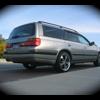
I’m sure word has travelled across the internet, that the Stagea has recently gone to a new home. While I was undecided whether to part ways with it or not over the course of a few months, I finally decided the time had come.

Everyone remembers my horrible R33 skyline that f**ked my life. Well I’ve still been trying to recover from the debts that it put me in. Whilst if I was smart enough I shouldn’t have built the Stagea as quick as I did. But not having something to track for so long really got to me. I think about it sometimes and regret using the money I got back from parting out the Skyline, to build the Stagea to a degree. But hey, you can’t change the past.


Anyway, along with that I’ve got other things going on which quite frankly are more important than a piece of metal on wheels. With all that said, it wasn’t an easy decision. I had never intended to sell the Stagea and if I wasn’t stuck in the rutt that I’ve been in for a while then it would still be in my possession.

I guess what gets to me the most is that it was oh so close to being ‘complete’ but I guess that is part of the parcel.

Stagea-driving-off.jpg

The new owner, Brad contacted me soon after I had advertised it for sale, we teed up to meet on Saturday. The cash was handed down, and the papers were signed. The Stagea was no longer mine.

Brad vowed to take good care of it, and I believe him. I’m glad it has gone to a good home where some will appreciate it for what it is. Maybe one day when I have my priorities right and a wad of cash burning in my pocket, I’ll build another Stagea.

Cya later LOLVO!

  • 1 year later...

Yes it's adams old stagea. Was great when he had it and it's gone down hill again, even after he bought it back and fixed it again.

When ever it gets sold the new owner wants to flog it off for more than they paid. New bloke is the worst, seen it for sale everywhere!

  • 6 years later...

Oh man I love this thread. I only just found it and wish more of the picture links still worked, or the website he linked was still up. Definitely some big inspiration for my stagea!

Create an account or sign in to comment

You need to be a member in order to leave a comment

Create an account

Sign up for a new account in our community. It's easy!

Register a new account

Sign in

Already have an account? Sign in here.

Sign In Now


  • Similar Content

  • Latest Posts

    • From there, it is really just test and assemble. Plug the adapter cables from the unit into the back of the screen, then the other side to the car harness. Don't forget all the other plugs too! Run the cables behind the unit and screw it back into place (4 screws) and you should now have 3 cables to run from the top screen to the android unit. I ran them along the DS of the other AV units in the gap between their backets and the console, and used some corrugated tubing on the sharp edges of the bracket so the wires were safe. Plug the centre console and lower screen in temporarily and turn the car to ACC, the AV should fire up as normal. Hold the back button for 3 sec and Android should appear on the top screen. You need to set the input to Aux for audio (more on that later). I put the unit under the AC duct in the centre console, with the wifi antenna on top of the AC duct near the shifter, the bluetooth antenna on the AC duct under the centre console The GPS unit on top of the DS to AC duct; they all seem to work OK there are are out of the way. Neat cable routing is a pain. For the drive recorder I mounted it near the rear view mirror and run the cable in the headlining, across the a pillar and then down the inside of the a pillar seal to the DS lower dash. From there it goes across and to one USB input for the unit. The second USB input is attached to the ECUtec OBD dongle and the 3rd goes to the USB bulkhead connected I added in the centre console. This is how the centre console looks "tidied" up Note I didn't install the provided speaker, didn't use the 2.5mm IPod in line or the piggyback loom for the Ipod or change any DIP switches; they seem to only be required if you need to use the Ipod input rather than the AUX input. That's it, install done, I'll follow up with a separate post on how the unit works, but in summary it retains all factory functions and inputs (so I still use my phone to the car for calls), reverse still works like factory etc.
    • Place the new daughterboard in the case and mount it using the 3 small black rivets provided, and reconnect the 3 factory ribbon cables to the new board Then, use the 3 piggyback cables from the daughterboard into the factory board on top (there are stand offs in the case to keep them apart. and remember to reconnect the antenna and rear cover fan wires. 1 screw to hold the motherboard in place. Before closing the case, make a hole in the sticker covering a hole in the case and run the cable for the android unit into the plug there. The video forgot this step, so did I, so will you probably. Then redo the 4 screws on back, 2 each top and bottom, 3 each side and put the 2 brackets back on.....all ready to go and not that tricky really.      
    • Onto the android unit. You need to remove the top screen because there is a daughterboard to put inside the case. Each side vent pops out from clips; start at the bottom and carefully remove upwards (use a trim remover tool to avoid breaking anything). Then the lower screen and controls come out, 4 screws, a couple of clips (including 3 flimsy ones at the top) and 3 plugs on the rear. Then the upper screen, 4 screws and a bunch of plugs and she is out. From there, remove the mounting brackets (2 screws each), 4 screws on the rear, 2 screws top and bottom and 3 screws holding in the small plates on each side. When you remove the back cover (tight fit), watch out for the power cable for the fan, I removed it so I could put the back aside. The mainboard is held in by 1 screw in the middle, 1 aerial at the top and 3 ribbon cables. If you've ever done any laptop stuff the ribbon cables are OK to work with, just pop up the retainer and they slide out. If you are not familiar just grab a 12 year old from an iphone factory, they will know how it works The case should now look like this:
    • Switching the console was tricky. First there were 6 screws to remove, and also the little adapter loom and its screws had to come out. Also don't forget to remove the 2 screws holding the central locking receiver. Then there are 4 clips on either side....these were very tight in this case and needed careful persuading with a long flat screw driver....some force required but not enough to break them...this was probably the fiddliest part of the whole job. In my case I needed both the wiring loom and the central locking receiver module to swap across to the new one. That was it for the console, so "assembly is the reverse of disassembly"
    • But first....while I was there, I also swapped across the centre console box for the other style where the AV inputs don't intrude into the (very limited !) space.  Part# was 96926-4GA0A, 284H3-4GA0B, 284H3-4GA0A. (I've already swapped the top 12v socket for a USB bulkhead in this pic, it fit the hole without modification:) Comparison of the 2: Basically to do the console you need to remove the DS and PS side console trim (they slide up and back, held in by clips only) Then remove the back half of the console top trim with the cupholders, pops up, all clips again but be careful at the front as it is pretty flimsy. Then slide the shifter boot down, remove the spring clip, loose it forever somewhere in the car the pull the shift knob off. Remove the tiny plastic piece on DS near "P" and use something thin and long (most screwdrivers won't fit) to push down the interlock and put the shifter down in D for space. There is one screw at the front, then the shifter surround and ashtray lift up. There are 3 or 4 plugs underneath and it is off. Next is the rear cover of the centre console; you need to open the console lid, pop off the trim covering the lid hinge and undo the 2rd screw from the driver's side (the rest all need to come out later so you can do them all now and remove the lid) Then the rear cover unclips (6 clips), start at the top with a trim tool pulling backwards. Once it is off there are 2 screws facing rearwards to remove (need a short phillips for these) and you are done with the rear of the console. There are 4 plugs at the A/V box to unclip Then there are 2 screws at the front of the console, and 2 clips (pull up and back) and the console will come out.
×
×
  • Create New...