Jump to content
SAU Community

Recommended Posts

make sure you keep the restrictor in the breather hoses, it is there for a reason

Do all RB engines have that or just 26's? When I setup my breather system I looked for a restrictor in the stock breather hoses and there was nothing...

  • Replies 43
  • Created
  • Last Reply

Top Posters In This Topic

Top Posters In This Topic

Posted Images

Do all RB engines have that or just 26's? When I setup my breather system I looked for a restrictor in the stock breather hoses and there was nothing...

As far as i know its only the 26 that has that on there, i know my 20 doesn't and i'm fairly confident the 25 doesn't either.

I highly suggest you read this, as it has pretty much all the answers to your questions thumbsup.gif

http://www.skylinesaustralia.com/forums/topic/314402-project-rb31dett-the-development-of-my-open-deck-rb-engine-and-the-quest-for-more-torque/page__view__findpost__p__6039475

Will this be efficient?

*excluding the breather though.

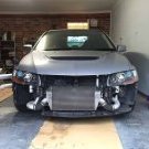
IMG_0196.jpg

No!. All this is doing is blowing the exh side gasses straight back to the turbo intake, totally defeating the purpose of installing the catch can - more correctly "oil-air-separator".

Leave the "U" hose connecting the 2 rocker covers. Disconnect the hose going from the exh cover down to the intake side of the turbo, and re-direct that to the catch can. Run the other fitting on the catch can back to the inlet side of the turbo. Simple.

Edited by blind_elk

Do all RB engines have that or just 26's? When I setup my breather system I looked for a restrictor in the stock breather hoses and there was nothing...

My 20 had a brass restrictor in the return pipe to the intake for the factory breather setup

No!. All this is doing is blowing the exh side gasses straight back to the turbo intake, totally defeating the purpose of installing the catch can - more correctly "oil-air-separator".

Leave the "U" hose connecting the 2 rocker covers. Disconnect the hose going from the exh cover down to the intake side of the turbo, and re-direct that to the catch can. Run the other fitting on the catch can back to the inlet side of the turbo. Simple.

Thanks alot man. That's all I wanted to know haha.

On my old gtr I had the autech style oil/air separator that sits ontop of the cam covers,

My new gtr has the pcv blocked, oil return to turbo inlet blocked and just running 2 hoses from cam covers to an atmo catch can, anything wrong with this besides been illegal?

Not a huge fan of this setup but that catch can/washer bottle fills the spot where the battery was (battery is relocated to boot)

The advantage of having the catch can breather connected to an intake is that it creates suction and helps clear the vapours better. This requires a proper catch can which functions as an oil/air seperator or a seperate oil /air seperator (you don't have to buy the Nismo ones - Moroso do them cheaper or you could have one fabricated) in the line. If you are having a catch can made you can specify proper baffling. Some catch cans have removable tops and bottoms and you can check and modify them yourself if necessary. Some ebay catch cans are so small and useless as to be for show only.

If you have heaps of blow by for what ever reason and the catch can set up you have is not coping then you will not want to feed this into your intake. Preferably you will fix the problem or modify your system to deal with it but (in NZ anyway) you can vent to atmosphere for track cars.

I have seen the engine bays of a number of Japanese race cars that have air oil seperators and one or two catch cans and run the breathers into the intake.

Indeed the good old steel wool in a stocking will be going inside the can.

This does f**k all, trust me. It's more likely to leave you with bits of disintegrated stocking and metal fibers in your intake then separate any oil from the air.

You have a GTR, give it the parts it deserves and get a properly baffled catch can. I got my custom combined 2L catch can/radiator overflow bottle from Pro Fabrications for $390 delivered, Brad is a good bloke and knows exactly what he is doing. Spend a bit more cash and do it right.

426487_10150508799027541_519882540_9106071_909800602_n.jpg

Edited by Hanaldo

i have a catch tank just like the one above n seems to work well.

i have a drain hole at the bottom of the can and i also have a spare fitting on the bottom of my extended sump.

if i was to run a braided line from the can directly to the sump would this be effective? or will oil from my sump just run up that line back towards the can?

When we do a sump & catch can for the same vehicle I always suggest a breather hose from a high point of the sump above oil level to the base of the catch can.

It just provides a better vent for the crankcase not a drain for the catch can.

This does f**k all, trust me. It's more likely to leave you with bits of disintegrated stocking and metal fibers in your intake then separate any oil from the air.

You have a GTR, give it the parts it deserves and get a properly baffled catch can. I got my custom combined 2L catch can/radiator overflow bottle from Pro Fabrications for $390 delivered, Brad is a good bloke and knows exactly what he is doing. Spend a bit more cash and do it right.

I was waiting for this quote. Obviously Im looking for my best option. Not OH MY GOD NIIIIISSSSSMMMMOOOOOOO! haha.

Create an account or sign in to comment

You need to be a member in order to leave a comment

Create an account

Sign up for a new account in our community. It's easy!

Register a new account

Sign in

Already have an account? Sign in here.

Sign In Now


  • Similar Content

  • Latest Posts

    • Sounds like the rack seals blew.
    • ^ This is all good advice. I can imagine that there's some passive components in the HVAC controller that run that PWM output that could die, or suffer bad solder joints. It can be worth opening it up, taking a schmooze around looking for swollen electro caps, evidence of liquid escape anywhere, tracks that have been hot, lifted, cracked, etc. A DMM might not be suitable for seeing if the PWM output is pulsing. Might be too fast and too low voltage for a DMM to keep up. An analogue voltmeter might give a better hope. I use a handheld oscilloscope (<$100 from Aliexpress if you want something cheap). A DMM might see the voltage across the motor flicker. Otherwise, as above. If you can successfully see PWM action, then the control side should be good. If you can't see it with what you have, you might need to step up the instrumentation used, as above. Beyond that, and dbm7's advice on testing the motor directly, you're down to looking for broken wires, corroded connector pins, etc.
    • So Thanks for the comments etc. To follow up on this, we went down the path of fitting a divider down the middle of the external pipe that was added to the exhaust manifold and the divider went from very close to the external wastegate all the way up to the "V" part where the pipes from each side of the manifold joined. After this modification it was finally in a position to do the dyno-tune with some degree of success. Top end power was down about 10kw (250rwkw down to 240rwkw) I believe from previous but it seems to be more responsive lower down and at least it is now driveable and fun and back on the road to be enjoyed. Apparently the timing couldn't be run the same as it was running into knock and boost was down about 1psi. For all we know this could have been from the fuel being a bit older, or perhaps some slight complication from the new head gasket as we didn't have compression figures from before that mod to compare. I'm no mechanic and this is second hand info but I just wanted to follow-up to those that commented or read the original post with interest. After so many months of stuffing around this is a big win. The interesting part was most of the info around this was gained from information around Barra motors and not GTR as the manifold setup on the Barra with single turbo was more similar.  Thanks for those that helped with info. Regards Rob 
    • G'day ... first up, I very much doubt that's a resistor network (as used also for this job), but the part# looks right. The description of 'power module assembly' looks to be nissanese for 'PWM driven, ground switched, DC motor speed controller'.... the circuit in the schematic kinda infers that's the case... ...with the transistor symbol appearing in the unit described here as 'Fan Control Amp(lifier)'....being driven by pin20 on the HVAC unit,  and a feedback signal on pin19 from the motor negative terminal for some reason (might be motor fault detection, maybe they detect commutator switching to determine motor revs as well, I dunno)... but if they are  counting commutator spikes, a bad segment (or really worn brushes) will throw a spanner in the works... The motor itself will as said be brushed DC with segmented commutator, rated at 12VDC nominally ~ now-a-days I just unplug them, determine the positive wire, and hook them up to a variable power supply and find out how much current they draw, if they work etc etc ...you can also check for bad segments...ie; set the power supply up to feed 1volt @ 2amp max, then watch the wattage count as you slowly rotate the fan blower motor through a complete revolution ; any bad/dead segments will be clearly evident...some folks would just say determine the positive wire, and feed it battery voltage, and if fan spin, you've got a win...<grin>... well, at least that infers it should do something when plugged back in, and the HVAC unit commands it to run... and if it doesn't, you suspect the module, but you should check the PWM signal on pin20 is actually present, and if it is, blame the module ...  
    • Ah. OK. I take it back. I hadn't looked closely at the R33/4 arms and presumed that GKTech did as GKTech do everywhere else, which is to use sphericals there. The poly bushings are made to be 100% interchangeable, should use the standard bolt just fine. Every other bush in every other place in pretty much every other car, does.
×
×
  • Create New...