
Spline Drive - Opnions, facts, any failures??
Announcements
-
Similar Content
-
-
Latest Posts
-
 That was the first session so not a lot to take from the day. It was low 20s ambient and the coolant had got to 110 (and obviously had some pressure!) so that still needs to be addressed. I haven't downloaded the data yet but will. I had refilled the auto trans with Redline DT6 because it claimed the best viscosity I could find at 100o. It wasn't really long enough to get a good feel for that; while the trans got to 100o in the session it still wasn't shifting crisply as I hoped. I think I'll try a few more sessions before judging. No steering motor overheat but I'd hope not in only 1 session! But finally the suspension; it was night and day over the standard stuff and the car was a couple of seconds quicker on the same crappy tyres, which is a huge difference. I'll stick with that and get some sway bars and a mechanical diff sorted too and see how that all goes together
 -
 I guess it’s partially a compromise of how my car is used, wanting to be able to switch from drift to grip with track side on-car adjustment. Also partially with the way the knuckles are set there is more static camber but less dynamic camber gain.
 -
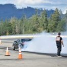
OK, so update from the track day on Friday It was a classic "an unfortunate series of events'. There were a few cars around and when i checked my mirror coming out of the fish hook I notice some smoke from the rear of mine. Looked again and it was getting much worse, I figured I'd blown a turbo or something to got off it and pulled off the racing line. However.... since it is a left hairpin into a right kink, I was on the inside of the next corner. There was a car passing me on the left and a big drop off over the ripple strip on the right......and someone had knocked the witch's hat that was on the apex about 1m onto the track. So, between those 3, I decided to mow down the cone and not damage my car/the other car. Right choice, but surprising result. The car decided the cone was a small pedestrian so it blew the rear bonnet hinges up to protect their head in the upcoming person to car impact....I didn't see that coming and like an airbag deployment it happened super fast. Straight into the pits from there, everything was driving fine but it became clear it was a coolant leak not smoke, it was billowing up onto the windscreen. Onto the trailer and home. I'll do a separate thread about the repair (once I work out what it is ), but the immediate problem was the bonnet wouldn't open because the front was pinched onto the front bar and would not release. Ultimately we unbolted the hinge from the bonnet, pulled it back a little and it released from the front OK. "There's your problem", the top radiator hose had popped off at the radiator.
-
Yeah that looks like great caster, but I'd suggest trying less front camber some time and seeing if it helps with braking without reducing mid corner speed too much
-
I ended up setting the rear 5mm higher than normal to give some clearance. My plan is to run the least camber I can in the rear which I think with the extra width is going to need to be -1.75 to -2.00° just to get clearance. Guards have been rolled and pulled as much as they can/I would be wanting to. front has the Acostal knuckle with the KPI change and the drop etc. So should be okay with the existing settings I have run with AR1s etc Front: Toe total -2mm(1mm out each side) Caster +7.5° Camber -3.8° Ackerman +15°
-


Recommended Posts
Create an account or sign in to comment
You need to be a member in order to leave a comment
Create an account
Sign up for a new account in our community. It's easy!
Register a new accountSign in
Already have an account? Sign in here.
Sign In Now