
What Have You Done To Your Stagea Lately?

Announcements
-
Similar Content
-
-
Latest Posts
-
 A 1.5 way is a 2 way. It is just a 2 way with a less aggressive ramp on overrun.
 -
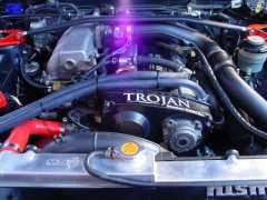
The ABS and/or TCS being missing/broken will not cause the engine to misbehave. It just casues CEL to come on and annoy you. The CEL is useless if it is always on, so you have to do the things you have to do to get rid of it, so it can be useful. Being a Stag ECU, then yes, it will not expect TCS to be present. But it will expect ABS to be present and working. You will need to either make the ABS CU talk to the ECU (don't ask me what that will take on an NA R34), and make sure the hardware is working....or, you just need to blank it out in Nistune. Do not persist with the stock ECU. You will just have problems. Gte it Nistuned. Start from there. DO YOU HAVE A BOOST SENSOR? The ECU's boost sensor that it. It is connected to the loom at the rear of the coil cover. Usually rides on the firewall on an R34, but is usually bolted down to a bracket along with all the other crap at the back of the coil cover when a Neo is dropped into another car. If you do not have it, the ECU will shit the bed. So, do you have one?
-
 So sadly the fuel pump etc was not it. The pump and filter is new and it is still cutting around 4000 rpm. A read something about ABS/TCS (engine is from stagea and ECU too so no TCS) and i dont know for 100% that my car has ABS. It has ABS "cube" in engine bay but i dont think it works(or at least from my braking experience). Can be something like that? I will be driving the car next week to Nistune tuner to properly see what is wrong...
 -
 the Tomei LSD fluid with lsd kit. frustrated that it was shaking the car to crap and affecting everything else negatively, I pulled the diff last night, and removed the lsd carrier, could not find anything wrong, however it seem to be 100 locked up acceleration, and deacceleration, wondering if they sent me a 2 way not a 1.5?? either way I installed the stock open carrier back in place. test drove everything smooth as butter again. no shake, shutter, random, what felt like clutch slip and grab or drive shaft play, etc. something differently wrong in side the lsd. I might bother taking it apart (if possible) to figure out what's going on inside this carrier, as bought too long ago to return. only draw back is its back to a one wheel wonder.
 -

By TurboTapin · Posted
What a time to be alive!!
-


Recommended Posts
Create an account or sign in to comment
You need to be a member in order to leave a comment
Create an account
Sign up for a new account in our community. It's easy!
Register a new accountSign in
Already have an account? Sign in here.
Sign In Now