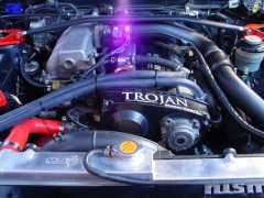
What Have You Done To Your Stagea Lately?
Announcements
-
Similar Content
-
Latest Posts
-
God damnit. The only option I actually have in the software is the one that is screenshotted. I am glad that I at least got it right... for those two points. Would it actually change anything if I chose/used 80C and 120C as the two points instead? My brain wants to imagine the formula put into HPtuners would be the same equation, otherwise none of this makes sense to me, unless: 1) The formula you put into VCM Scanner/HPTuners is always linear 2) The two points/input pairs are only arbitrary to choose (as the documentation implies) IF the actual scaling of the sensor is linear. then 3) If the scaling is not linear, the two points you choose matter a great deal, because the formula will draw a line between those two points only.
-
Nah, that is hella wrong. If I do a simple linear between 150°C (0.407v) and 50°C (2.98v) I get the formula Temperature = -38.8651*voltage + 165.8181 It is perfectly correct at 50 and 150, but it is as much as 20° out in the region of 110°C, because the actual data is significantly non-linear there. It is no more than 4° out down at the lowest temperatures, but is is seriously shit almost everywhere. I cannot believe that the instruction is to do a 2 point linear fit. I would say the method I used previously would have to be better.
-
When I said "wiring diagram", I meant the car's wiring diagram. You need to understand how and when 12V appears on certain wires/terminals, when 0V is allowed to appear on certain wires/terminals (which is the difference between supply side switching, and earth side switching), for the way that the car is supposed to work without the immobiliser. Then you start looking for those voltages in the appropriate places at the appropriate times (ie, relay terminals, ECU terminals, fuel pump terminals, at different ignition switch positions, and at times such as "immediately after switching to ON" and "say, 5-10s after switching to ON". You will find that you are not getting what you need when and where you need it, and because you understand what you need and when, from working through the wiring diagram, you can then likely work out why you're not getting it. And that will lead you to the mess that has been made of the associated wires around the immobiliser. But seriously, there is no way that we will be able to find or lead you to the fault from here. You will have to do it at the car, because it will be something f**ked up, and there are a near infinite number of ways for it to be f**ked up. The wiring diagram will give you wire colours and pin numbers and so you can do continuity testing and voltage/time probing and start to work out what is right and what is wrong. I can only close my eyes and imagine a rat's nest of wiring under the dash. You can actually see and touch it.
-
So I found this: https://www.efihardware.com/temperature-sensor-voltage-calculator I didn't know what the pullup resistor is. So I thought if I used my table of known values I could estimate it by putting a value into the pullup resistor, and this should line up with the voltages I had measured. Eventually I got this table out of it by using 210ohms as the pullup resistor. 180C 0.232V - Predicted 175C 0.254V - Predicted 170C 0.278V - Predicted 165C 0.305V - Predicted 160C 0.336V - Predicted 155C 0.369V - Predicted 150C 0.407V - Predicted 145C 0.448V - Predicted 140C 0.494V - Predicted 135C 0.545V - Predicted 130C 0.603V - Predicted 125C 0.668V - Predicted 120C 0.740V - Predicted 115C 0.817V - Predicted 110C 0.914V - Predicted 105C 1.023V - Predicted 100C 1.15V 90C 1.42V - Predicted 85C 1.59V 80C 1.74V 75C 1.94V 70C 2.10V 65C 2.33V 60C 2.56V 58C 2.68V 57C 2.70V 56C 2.74V 55C 2.78V 54C 2.80V 50C 2.98V 49C 3.06V 47C 3.18V 45C 3.23V 43C 3.36V 40C 3.51V 37C 3.67V 35C 3.75V 30C 4.00V As before, the formula in HPTuners is here: https://www.hptuners.com/documentation/files/VCM-Scanner/Content/vcm_scanner/defining_a_transform.htm?Highlight=defining a transform Specifically: In my case I used 50C and 150C, given the sensor is supposedly for that. Input 1 = 2.98V Output 1 = 50C Input 2 = 0.407V Output 2 = 150C (0.407-2.98) / (150-50) -2.573/100 = -0.02573 2.98/-0.02573 + 47.045 = 50 So the corresponding formula should be: (Input / -0.02573) + 47.045 = Output. If someone can confirm my math it'd be great. Supposedly you can pick any two pairs of the data to make this formula.
-


Recommended Posts
Create an account or sign in to comment
You need to be a member in order to leave a comment
Create an account
Sign up for a new account in our community. It's easy!
Register a new accountSign in
Already have an account? Sign in here.
Sign In Now