

Announcements
-
Similar Content
-
-
Latest Posts
-
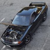
 Took longer than a weekend to get to it, but I finally took the time. The boost controller is in a different spot on the Stagea (between the battery and fuse box), but the hose with the yellow line was there. Sure enough, the restrictor was still in my car. Woot! 50% more boost for 20 mins and $0 USD ($0 AUD at current exchange rates 😜).
 -
 So just get it rebuilt and replace it with a genuine boot? Is it possible that I would have to replace the CV joint as well?
 -
 Okay I must of got my letters wrong instead of hp I’d like to make 450-600kw i know it’s quite easy to make it on an RB I already got the turbo for free so it’s brand new the aeroflow 62 .84 T51r mod already done T4 flange can I change it to a t3 but please tell me how
 -
 rebuilding is a straightforward option too, the only thing to keep in mind is non-genuine boots are likely to be much worse quality rubber and need replacing about 10x as often.
 -

By GoHashiriya · Posted
Yeah, great guy that Matt, giving very comprehensive emails with quick responses. He told me it’ll be plug and play for the ECU, which may potentially get me out on track at 600kph by the end of the month or June. Anyone wanna buy a HKS SLD..
-


Recommended Posts
Create an account or sign in to comment
You need to be a member in order to leave a comment
Create an account
Sign up for a new account in our community. It's easy!
Register a new accountSign in
Already have an account? Sign in here.
Sign In Now