
Announcements
-
Similar Content
-
-
Latest Posts
-

-
 Gday gents, been having a issue for a little while now and have come for some advice. car is a r34 gt-four (awd na sedan), when taking tight corners such as car parks and roundabouts feels as if the diff is locked on both ends, have literally snapped 3 shafts and issues doing my head in. Car has 60k klm so mechanical failure in the diff is unlikely but possible, been to 2 very reputable shops near where I live and both have had no luck. What would be my process of trying to find the cause? not too interested in pulling apart transfer cases just to find nothing, have these cars come out with electronic BS that might cause this? not too mechanically inclined so any information will probably be passed on an expert thanks in advance
 -

-
I realise that perhaps no one will in Japan will see this, but why not try anyway. What are you driving in Japan? I have a (sniff (;_;) ) 2018 Toyota Corolla Sports 1.2L Turbo 6MT. It has a class trailing 116PS and 190Nm power/torque... 😐 Why? Because back in 2018 there was only 1(?) manual transmission car available from Toyota which was the 86 (not including the Mark X GRMN 2015/2019), so when they released this one I had to support them by getting one in the hope that they would continue to release more manual models. As it turns out they released the Supra, Yaris, and GR Corolla all with manual transmissons after that. Mods are RSR Ti2000 Down springs, HKS panel filter, 18x8.5" Weds Sports SA-20R Face F with 215/40R18 Toyota Proxes Sport tyres. Eventually a full exhaust, boost controller sub-con, Blitz turbocharger and aero parts will be added before it gets replaced...
-
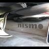
It looks proper factory fitted. It's exactly how I would do it. Well done 👍
-


Recommended Posts
Create an account or sign in to comment
You need to be a member in order to leave a comment
Create an account
Sign up for a new account in our community. It's easy!
Register a new accountSign in
Already have an account? Sign in here.
Sign In Now